Capacitive position sensing for transducers

Active Publication Date: 2016-03-31
APPLE INC
View PDF3 Cites 158 Cited by
  • Summary
  • Abstract
  • Description
  • Claims
  • Application Information

AI Technical Summary

Benefits of technology

[0008]In an embodiment, a sensing circuit may be electrically connected with each variable capacitor, and more particularly, with the capacitive plate sections. That is, electrical leads may extend from respective capacitive plate sections to electrically connect the capacitive plate sections with the sensing circuit. In an embodiment, pairs of the variable capacitors may be electrically in series through the diaphragm. Furthermore, the sensing circuit may connect with multiple groups of the serially connected variable capacitor pairs. Thus, the electrical leads may convey signals for the variable capacitor pairs to the sensing circuit. Those signals may correspond to capacitance of the variable capacitors. Thus, the sensing circuit may be configured to measure the capacitance and to calculate displacement and position of the diaphragm based on the signals. Monitoring diaphragm position in this way may avoid speaker damage or undesirable acoustic distortion, given that the micro speaker may include limited available travel for the diap

Problems solved by technology

Monitoring diaphragm position in this way may avoid speaker damage or undesirable acoustic di

Method used


Image

  • Capacitive position sensing for transducers
  • Capacitive position sensing for transducers
  • Capacitive position sensing for transducers

Examples


Embodiment Construction

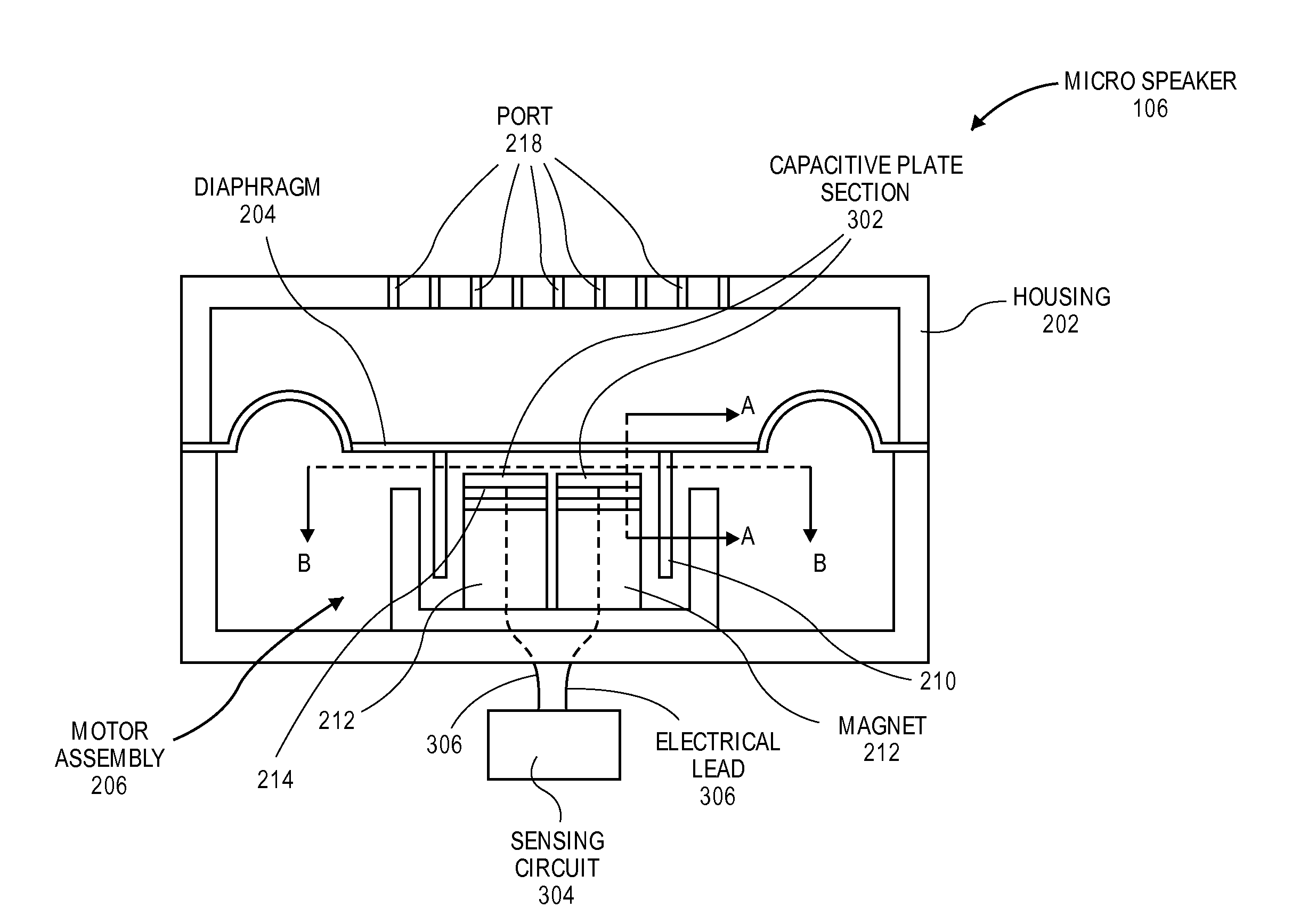
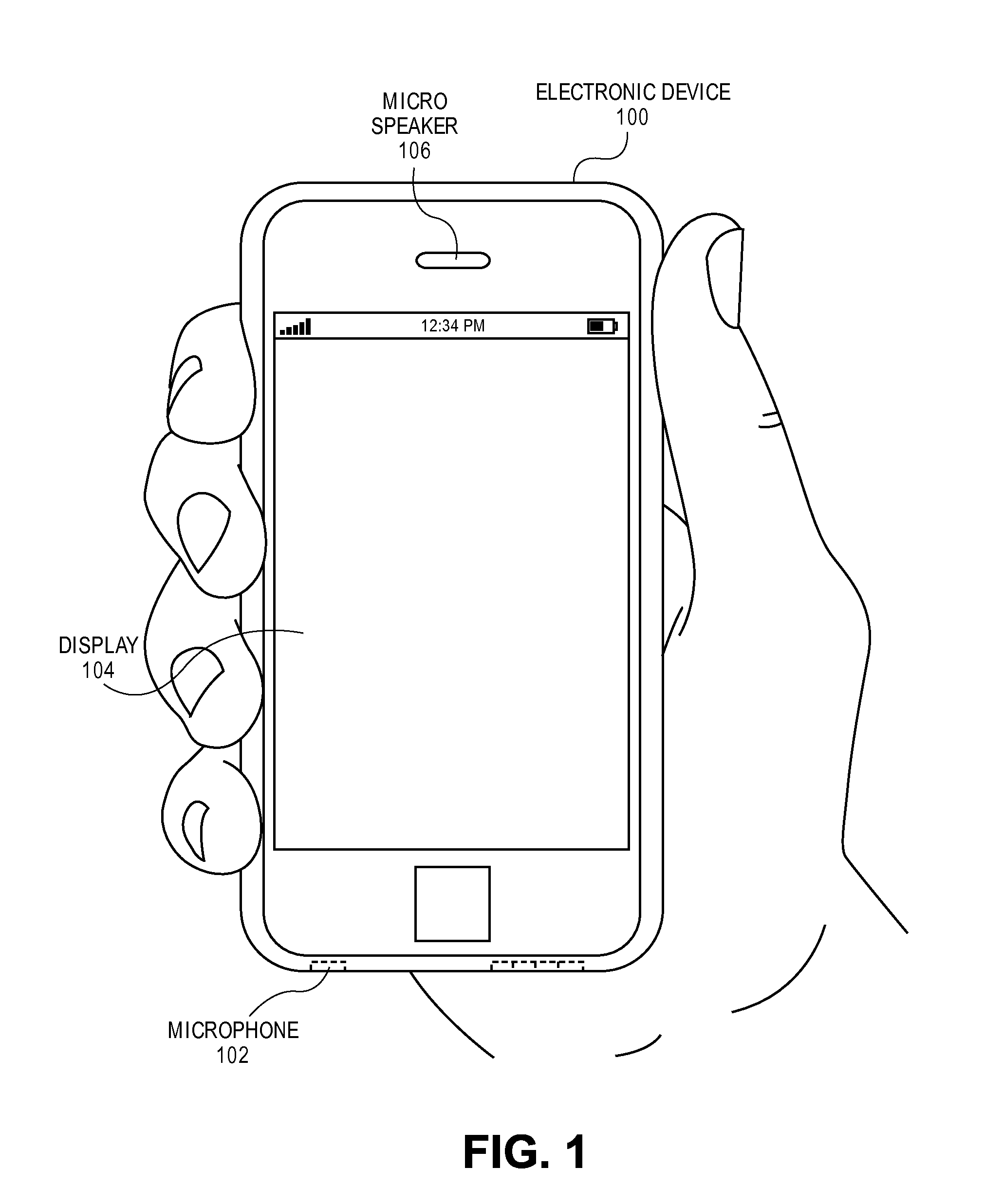
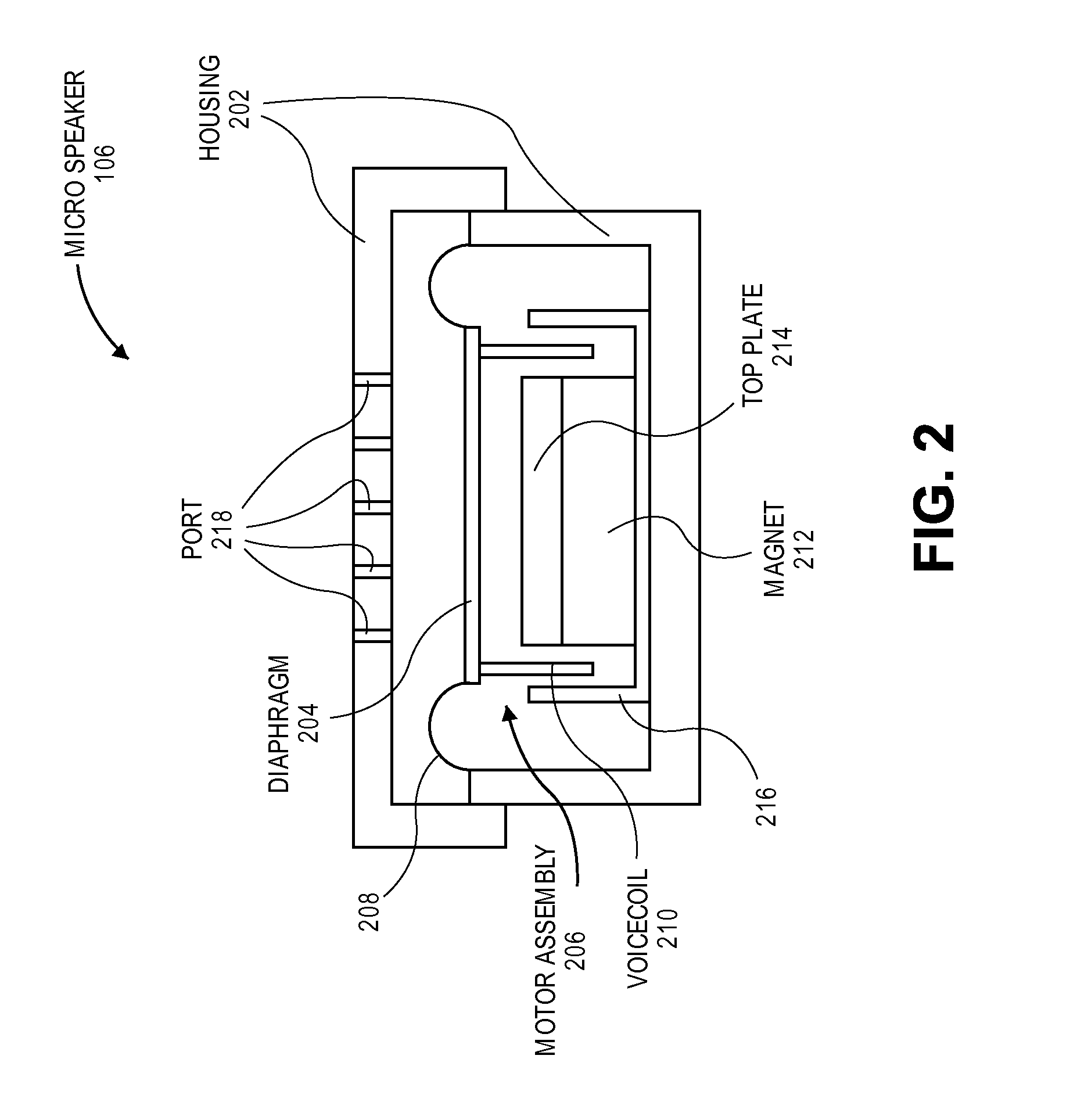
[0020]Embodiments describe micro speakers having a capacitive sensor to determine a motion of a speaker diaphragm, particularly for use in portable consumer electronics device applications. However, while some embodiments are described with specific regard to integration within mobile electronics devices such as handheld devices, the embodiments are not so limited and certain embodiments may also be applicable to other uses. For example, a micro speaker as described below may be incorporated into headphones. Furthermore, the micro speaker may be incorporated into systems that remain at a fixed location, e.g., an automated teller machine, or used in a relatively stationary application, e.g., as part of a car infotainment system.

[0021]In various embodiments, description is made with reference to the figures. However, certain embodiments may be practiced without one or more of these specific details, or in combination with other known methods and configurations. In the following descri...


PUM


Abstract

A micro speaker having a capacitive sensor to sense a motion of a speaker diaphragm, is disclosed. More particularly, embodiments of the micro speaker include a conductive surface of a diaphragm facing conductive surfaces of several capacitive plate sections across a gap. The diaphragm may be configured to emit sound forward away from a magnet of the micro speaker, and the capacitive plate sections may be supported on the magnet behind the diaphragm. In an embodiment, the gap provides an available travel for the diaphragm, which may be only a few millimeters. A sensing circuit may sense capacitances of the conductive surfaces to limit displacement of the diaphragm to within the available travel.

Description

[0001]This application claims the benefit of U.S. Provisional Patent Application No. 62 / 057,743, filed Sep. 30, 2014, and this application hereby incorporates herein by reference that provisional patent application.BACKGROUND[0002]1. Field[0003]Embodiments related to an audio speaker having a capacitive sensor to sense motion of a speaker diaphragm are disclosed. More particularly, an embodiment related to a micro speaker having a diaphragm that emits sound forward away from a motor assembly, is disclosed.[0004]2. Background Information[0005]An audio speaker driver converts an electrical audio input signal into an emitted sound. Audio speaker drivers typically include a diaphragm connected with a motor assembly, e.g., a voicecoil and a magnet. Thus, when the electrical audio input signal is input to the voicecoil, a mechanical force may be generated that moves the diaphragm to generate sound. Loudspeaker drivers may be divided into two broad classes—“direct radiators”, which couple ...

Claims


Application Information

Patent Timeline
IPC IPC(8): H04R9/02H04R7/16
CPCH04R7/16H04R9/02H04R3/007H04R9/06H04R2499/11
Inventor WILK, CHRISTOPHERSALVATTI, ALEXANDER, V.JENSEN, THOMAS, M.PORTER, SCOTT, P.DAVE, RUCHIR, M.BRIGHT, ANDREW, P.HOGAN, RODERICK, B.
Owner APPLE INC
Why Eureka
Try Eureka