
Semantic manufacturing

a manufacturing method and manufacturing method technology, applied in the field of data analysis and visualization, can solve the problems of added cost and/or delay in the design cycle, the process required to manufacture the item is too expensive and/or too time-consuming, and the secondary issue of manufacturing such an item

Inactive Publication Date: 2016-04-07
GENERAL ELECTRIC CO
View PDF4 Cites 5 Cited by
  • Summary
  • Abstract
  • Description
  • Claims
  • Application Information

AI Technical Summary

Benefits of technology

The patent text describes a system and method for automatically identifying manufacturing features in computer-aided designed (CAD) and comparing them to semantic manufacturing rules. The system uses a semantic graph to represent the relationships between data points in the CAD design and compares them to a repository of semantic rules to determine if the design is manufacturable. The technical effect of the system is to provide a user interface for designers to review any instances of manufacturing features and determine if they are not compliance with the rules, thus improving the manufacturability of the design.

Problems solved by technology

When designing an item to be manufactured, a designer may focus on the performance characteristics of the item; the manufacturing of such an item may be a secondary issue.
However, when a manufacturing analysis is later performed for the designed item, it may be discovered that the processes required to manufacture the item are too expensive and / or too time consuming.
The impact of the first option may include added cost and / or delays in the design cycle.
The impact of the second option may include a break in the link between design and manufacturing which may result in performance issues if the manufacturer is not careful.
For example, the proposed item design may modified in view of an excessively high cost to manufacture the item because expensive machinery may be required to produce a bend with the originally designed characteristics.

Method used


Image

  • Semantic manufacturing
  • Semantic manufacturing
  • Semantic manufacturing

Examples


example design process

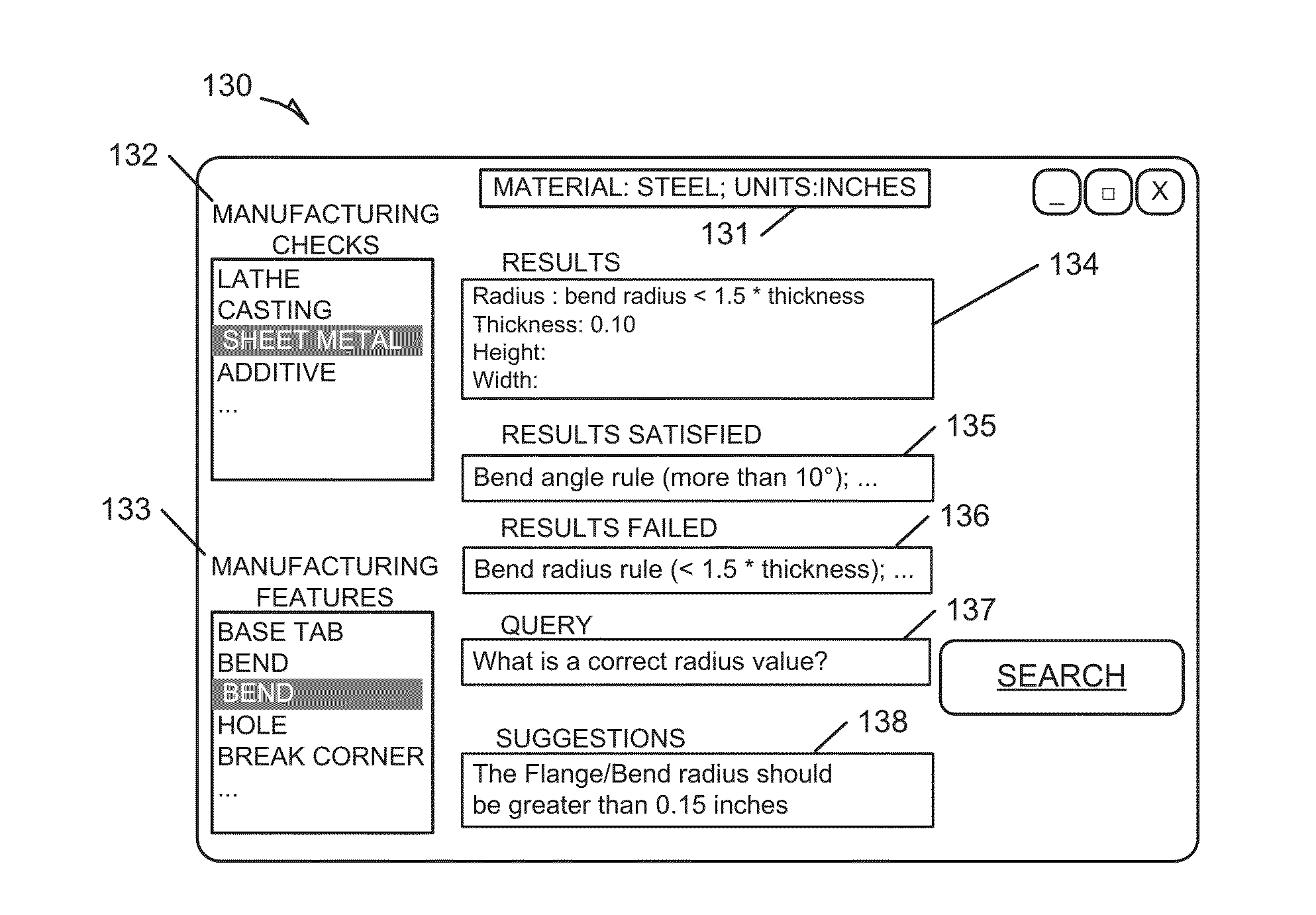
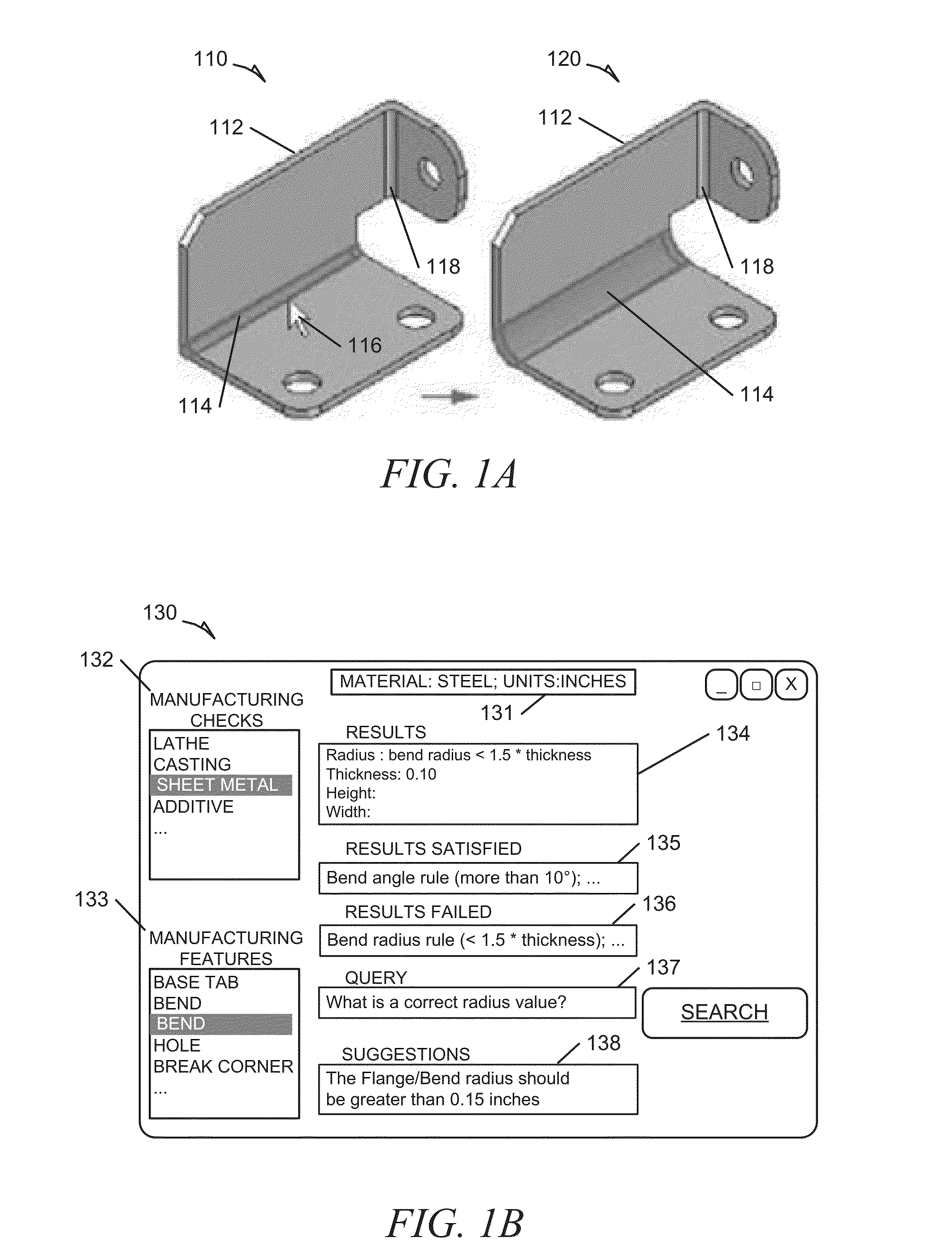
[0013]FIG. 1A illustrates an instance of a manufacturing feature being flagged at the design stage for not complying with a set of semantic manufacturing rules and includes an image 110 of an example item 112 being designed using a CAD application. In the given example, the item 112 is to be manufactured from a section of sheet metal, e.g., metal formed by an industrial process into thin, flat pieces. As shown in image 110, the design of the item 112 requires a bend 114 in the sheet metal to provide an approximately 90° angle. The bend 114 is highlighted at 116 by the CAD application so as to warn a designer about any potential problems or challenges with the manufacturing characteristics of the proposed design for the item 112. The bend 116 may then be altered by the designer in view of the concerns regarding the manufacturability of the proposed design for the item. For example, the proposed item design may modified in view of an excessively high cost to manufacture the item becau...

example feature

Recognition

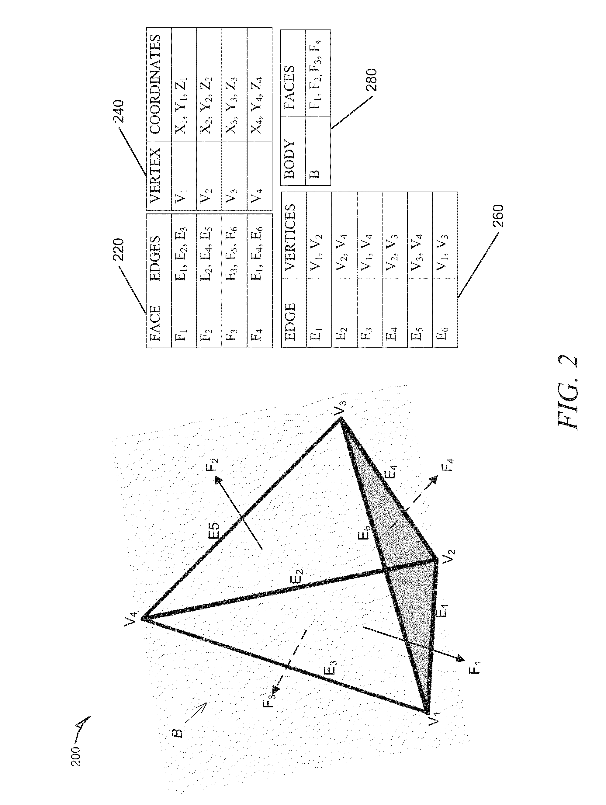
[0024]FIG. 2 includes an example BREP model 200 and associated data tables (220, 240, 260, 280) for the body, faces, edges and vertices of the BREP model 200 that may be analyzed and processed by a semantic processor 406 in accordance with the systems and methods presented herein. The relationships between the topological elements of BREP model 200 are stored in the tables 220, 240, 260 and 280. For example, face F1 of BREP model 200 has corresponding edges E1, E2, and E3. The table 240 illustrates geometric information regarding each vertex (V1-V4) of BREP model 200: corresponding (x, y and z axis) numerical coordinates.

[0025]A manufacturing feature may be described as a set of BREP elements that has a special meaning to an end user designing an item for manufacture. It is usually a subset of the BREP of a body, or a sub-BREP. In an example, feature rules are rules describing this sub-BREP. In an example, a triangle manufacturing feature may be recognized by a triangle r...


PUM


Abstract

A dataset including boundary representations of shapes associated with an item being designed for manufacture is accessed by a semantic processing module. A semantic graph of each of the boundary representations of shapes is generated and a numerical processing module computes geometric attributes of each of the shapes. The semantic graph of a shape is updated based on any geometric attributes computed for the shape. The semantic graphs are then compared to a repository of semantic graphs of manufacturing features to identify instances of manufacturing features. Geometric attributes associated with each instance of a manufacturing feature are then computed. For each instance, the associated geometric attributes are compared against a repository of semantic manufacturing rules to determine whether the instance is in compliance with the rules. A user designing the item is alerted to the presence of any instances of manufacturing features that are not in compliance with the rules.

Description

TECHNICAL FIELD[0001]This document relates generally to data analysis and visualization. More particularly, but not by way of limitation, to systems and methods for automatically identifying manufacturing features in computer aided design (CAD) dataset and comparing the identified features against a set of semantic manufacturing rules.BACKGROUND[0002]When designing an item to be manufactured, a designer may focus on the performance characteristics of the item; the manufacturing of such an item may be a secondary issue. However, when a manufacturing analysis is later performed for the designed item, it may be discovered that the processes required to manufacture the item are too expensive and / or too time consuming. A first option may include the designer updating the item design to improve its characteristics of manufacturability, leading to more design iterations. A second option may include the manufacturer choosing not to follow the design because of the expense or other manufactu...

Claims


Application Information

Patent Timeline
IPC IPC(8): G05B19/4097
CPCG05B2219/35134G05B19/4097G05B2219/35028G05B2219/35032G05B2219/35088G05B2219/35193G06F30/17G06F2119/18Y02P90/02
Inventor SINGH, BALJITMOITRA, ABHAGRAHAM, MICHAEL EVANSROBINSON, DEAN MICHAELJIA, TAO
Owner GENERAL ELECTRIC CO
Learn More