Tube-Fitting-Assembly Ferrule

Active Publication Date: 2016-04-14
RIETH PATRICK L
View PDF1 Cites 0 Cited by
  • Summary
  • Abstract
  • Description
  • Claims
  • Application Information

AI Technical Summary

Benefits of technology

The present invention provides a ferrule seal assembly that combines high performance with overall fitting integrity and leak-proof performance. It minimizes the potential for connection blow-outs or blow-offs. The assembly includes a first tube fitting member, such as a valve or conduit, a second tube fitting member, such as an externally threaded nut, and a tube gripping member, such as a ferrule. The ferrule has sufficient plasticity to deform and seal with the tube end through a partial bending of the sealing portion.

Problems solved by technology

Such heavy wall tubing is difficult to grip because it is not only hard, but also resistant to deformation.
Such physical characteristics make it more difficult to deform the tubing plastically so as to achieve a desired tube grip.
In many known fitting assemblies, the resulting seal is less than adequate, requiring one or more elastomeric seals to prevent leakage of the liquid or gas.

Method used


Image

  • Tube-Fitting-Assembly Ferrule
  • Tube-Fitting-Assembly Ferrule
  • Tube-Fitting-Assembly Ferrule

Examples


Embodiment Construction

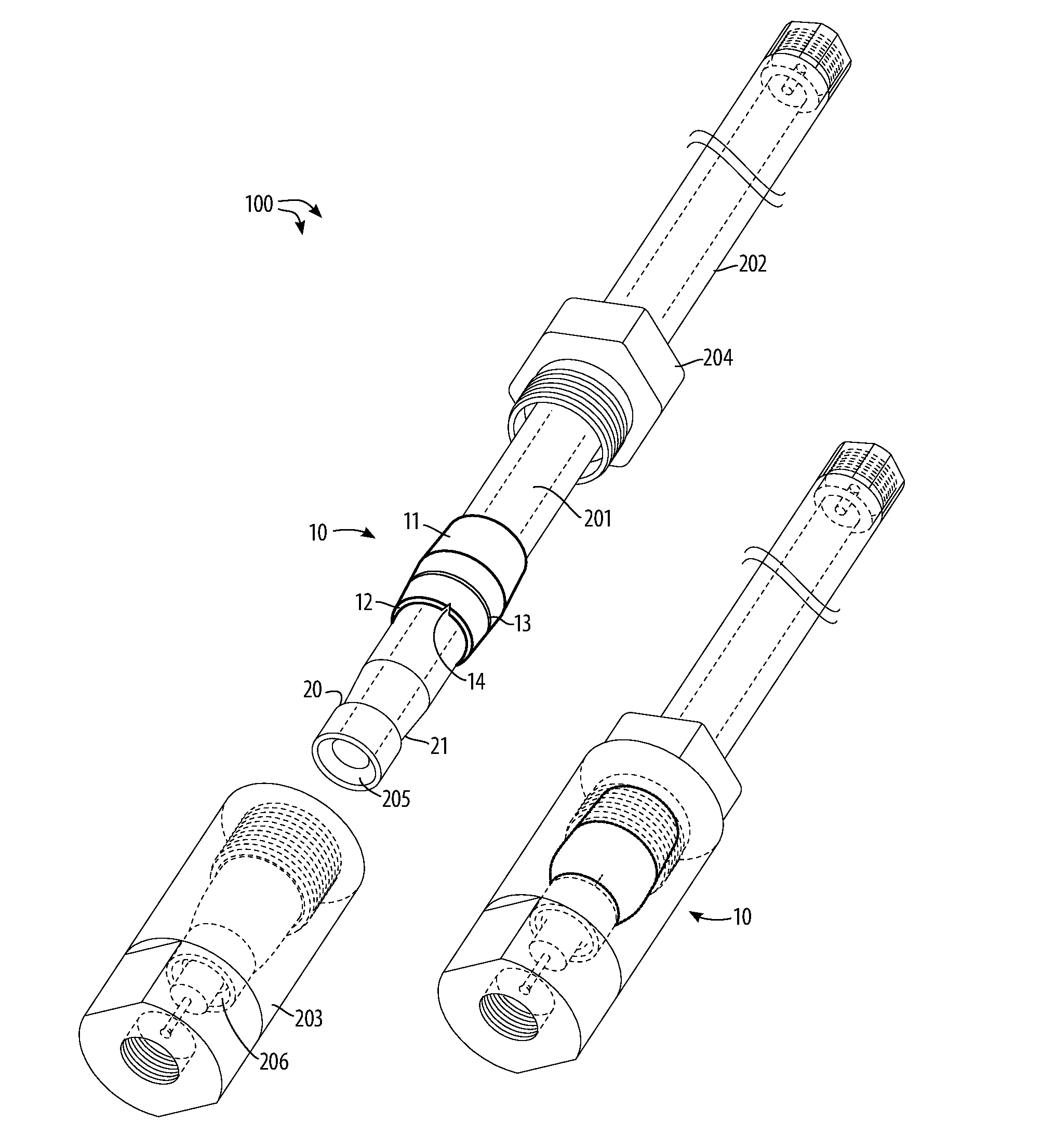
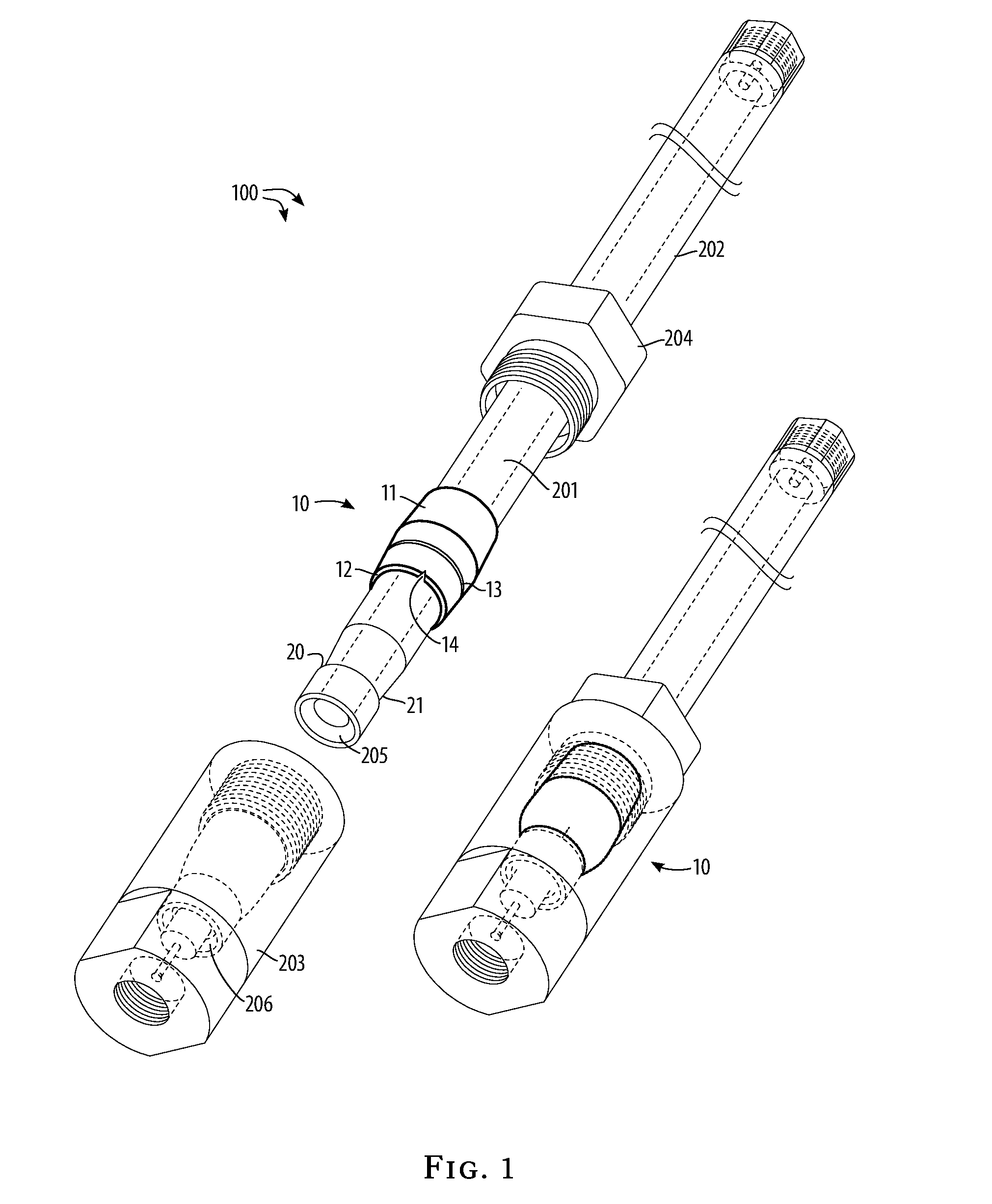
[0025]Referring to FIG. 1 and all figures generally, the tube-fitting-assembly method 100 and the tube-fitting-assembly ferrule apparatus 10 are shown in use schematically.

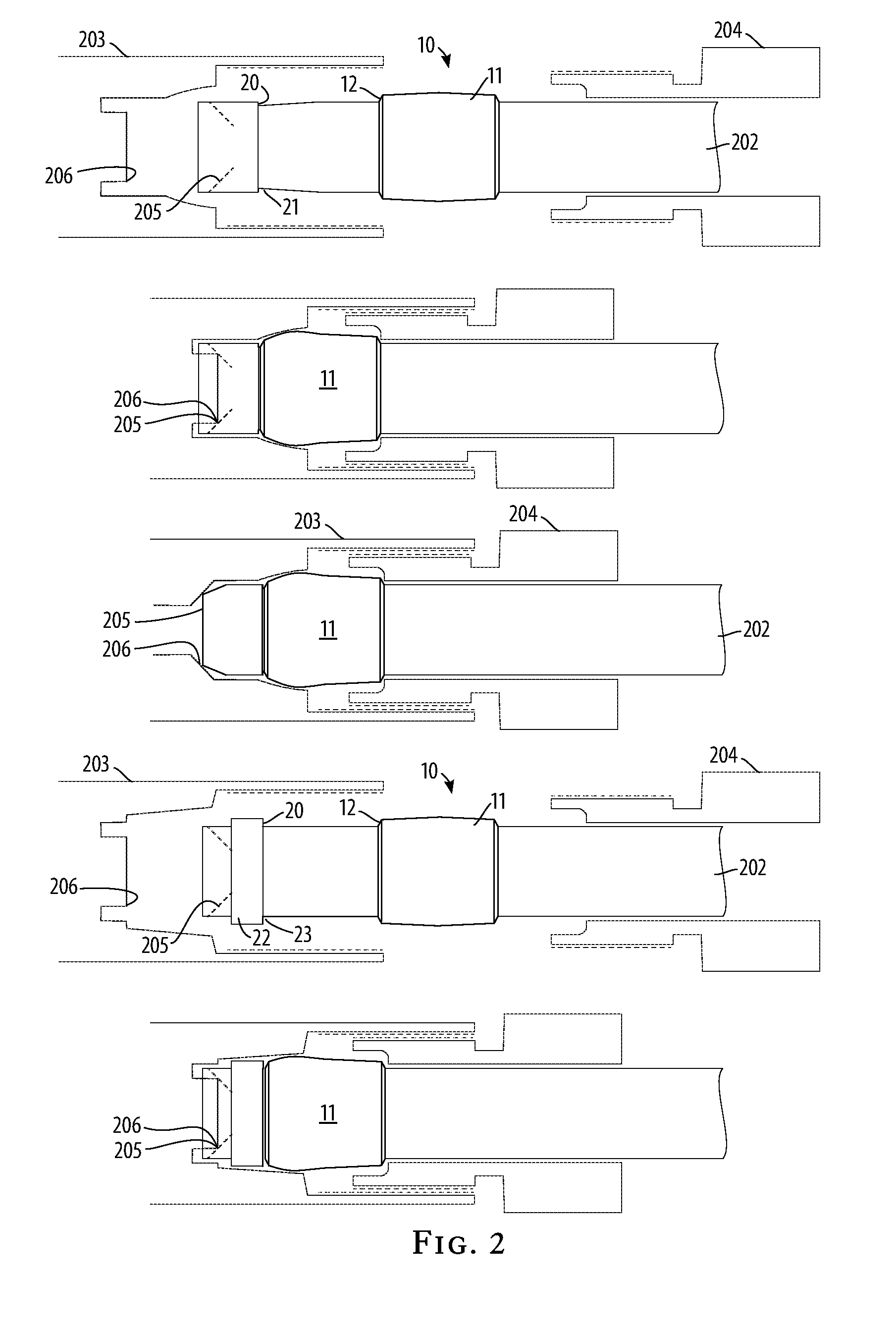
[0026]The invention is used with tubing, usually high-pressure tubing subject to vibrating, pulsating, or pounding, characterized by a tube channel 201 defined by a one or more tube-wall sections 202. The tubing sections are connected to other tubing sections or ultimately to devices by the operation of threaded sockets 203 and threaded plug-nuts 204. The end of the tube-wall section 202 is terminated with a section sealing surface 205 that seals against a socket sealing surface 206 that is built in to the threaded socket 203. The resulting seal is a point seal that circles the tube channel. It is this point seal that will be subjected to vibrating, pulsing, and pounding during normal operation of the tube assembly.

[0027]The invention provides a transverse shoulder 20 on the tube-wall section 202 near the section ...


PUM

PropertyMeasurementUnit
Distanceaaaaaaaaaa
Plasticityaaaaaaaaaa

Abstract

A tube-fitting-assembly ferrule apparatus and method to secure connections between tubing sections against high pressure, vibration, pulsation, and hammering, by providing a tube-fitting-assembly ferrule which elastically deforms in use, securing the primary circumferential point seal with a shock-absorbing and shape-retaining force.

Description

CROSS-REFERENCE TO RELATED APPLICATIONS[0001]This application is a continuation-in-part of my co-pending application Ser. No. 14 / 288,292 filed on May 27, 2014 and entitled “Tube Fitting Assembly,” which is a divisional of application Ser. No. 13 / 068,391 filed on May 10, 2011, which issued as U.S. Pat. No. 8,769,798 on Jul. 8, 2014 for a “Tube Fitting Assembly,” the full disclosures of which are incorporated by reference herein and priority of which are hereby claimed.BACKGROUND OF THE INVENTION[0002]This invention relates generally to the sealing of fittings about tubes and, more particularly, though not exclusively, to the sealing of tubing being a tube gripping member, such as a ferrule.[0003]Tube fittings are used to join or connect a tube end to another member, whether that other member be another tube end or a device in fluid communication with the tube end. Generally, tube fittings are designed to withstand operational conditions of the environment where the tube is located, s...

Claims


Application Information

Patent Timeline
IPC IPC(8): F16L19/02
CPCF16L19/02F16L19/0206F16L19/065Y10T29/49904Y10T29/49908Y10T29/49909Y10T29/49927Y10T29/49938Y10T29/49947Y10T29/49948Y10T29/53843Y10T29/53848Y10T29/53952Y10T29/53987
Inventor RIETH, PATRICK L.
Owner RIETH PATRICK L
Why Eureka
Try Eureka