Shoe light device capable of flashing in different modes and driving method thereof

Active Publication Date: 2022-03-24
FULLY ELECTRONICS CO LTD
View PDF0 Cites 0 Cited by
  • Summary
  • Abstract
  • Description
  • Claims
  • Application Information

AI Technical Summary

Benefits of technology

The shoe light device described in this patent has a motion sensor, light-emitting device, and integrated chip all integrated on the shoe. The integrated chip controls the light-emitting device to flash in a predetermined pattern when the motion sensor detects motion. This device has the advantages of being durable, easy to assemble, and having several modes of flashing.

Problems solved by technology

Common shoe light devices on the present market have the defects of complicated electrical structure, high standby power consumption (which is 3-5UA), low input voltage (which is 3-5V), complicated production process, difficult quality control, single flashing mode and incontrollable display brightness.

Method used


Image

  • Shoe light device capable of flashing in different modes and driving method thereof
  • Shoe light device capable of flashing in different modes and driving method thereof
  • Shoe light device capable of flashing in different modes and driving method thereof

Examples


embodiment 1

[0073]Referring to FIG. 1 to FIG. 18, Embodiment 1 of the invention is as follows:

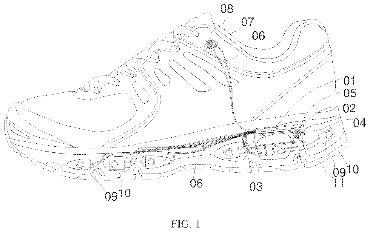
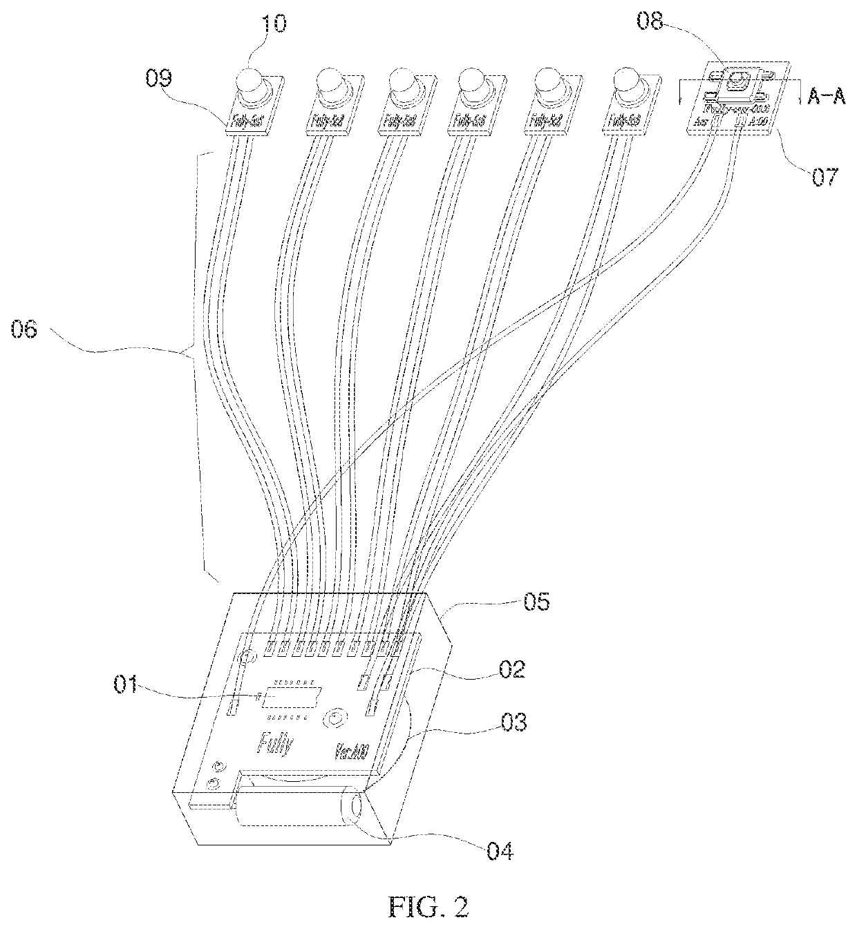
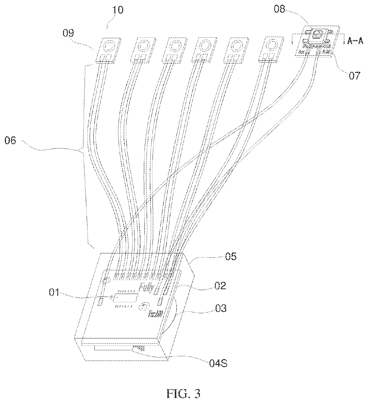
[0074]As shown in FIG. 1 to FIG. 4, the invention provides a shoe light device capable of flashing in different modes. The shoe light device capable of flashing in different modes comprises a motion sensor, an integrated chip and a light-emitting device, wherein the motion sensor is disposed at the bottom of a shoe, the integrated chip is disposed on the shoe, the light-emitting device is disposed on an outer wall of the shoe, and the motion sensor and the light-emitting device are electrically connected to the integrated chip; and the integrated chip is configured to control the light-emitting device to emit light in a preset constant-sequence output mode when the duration of reception of pulse signals generated by the motion sensor reaches a preset threshold.

[0075]As shown in FIG. 5 and FIG. 6, the motion sensor comprises a spindle, a spring and a shell, wherein the shell is a cylindrical shell, the ...

embodiment 2

[0260]Referring to FIG. 19, Embodiment 2 of the invention is as follows:

[0261]The invention further provides a driving method of the shoe light device capable of flashing in different modes. The driving method comprises the following steps:

[0262]When the motion sensor recognizes a resilience force generated at the moment the bottom of the shoe touches the ground, a series of pulse signals is sent to the integrated chip;

[0263]The integrated chip receives and counts the pulse signals, and the time at this moment is recorded to obtain the duration of reception of the pulse signals; and

[0264]The integrated chip determines whether or not the duration of reception of the pulse signals reaches a preset threshold; if so, the integrated chip controls the light-emitting device to emit light in a preset constant-sequence output mode.

[0265]Wherein, the preset threshold is 10 milliseconds.

[0266]Furthermore, the driving method further comprises the following steps:

[0267]The integrated chip receiv...


PUM


Abstract

The invention relates to the technical field of shoe lights; in particular, to a shoe light device capable of flashing in different modes and a driving method thereof. A motion sensor, an integrated chip and a light-emitting device are integrated on a shoe, and the motion sensor and the light-emitting device are electrically connected to the integrated chip. The integrated chip is configured to control the light-emitting device to emit light in a preset constant-sequence output mode when the duration of reception of pulse signals generated by the motion sensor reaches a preset threshold, so that trigger control over the light-emitting device is realized. The shoe light device capable of flashing in different modes has the advantages of high integrity of elements, simple structure, simple production process, and various integrated cyclic output modes for flashing of the light-emitting device.

Description

PRIORITY CLAIM[0001]In accordance with 37 C.F.R. 1.76, a claim of priority is included in an Application Data Sheet filed concurrently herewith. Accordingly, the present invention claims priority to U.S. Non-Provisional patent application Ser. No. 17 / 029,207, entitled “SHOE LIGHT DEVICE CAPABLE OF FLASHING IN DIFFERENT MODES AND DRIVING METHOD THEREOF”, filed Sep. 23, 2020. The contents of the above referenced application are incorporated herein by reference in its entirety.TECHNICAL FIELD[0002]The invention relates to the technical field of shoe lights, in particular to a shoe light device capable of flashing in different modes and a driving method thereof.DESCRIPTION OF RELATED ART[0003]Common shoe light devices on the present market have the defects of complicated electrical structure, high standby power consumption (which is 3-5UA), low input voltage (which is 3-5V), complicated production process, difficult quality control, single flashing mode and incontrollable display bright...

Claims


Application Information

Patent Timeline
IPC IPC(8): H05B47/17F21S10/06A43B3/00F21S9/02F21V23/00H01H13/14F21V23/04H05B45/10H01H1/14
CPCH05B47/17F21S10/06A43B3/001F21S9/02F21V23/007F21Y2115/10F21V23/0492F21V23/0407H05B45/10H01H1/14H01H13/14H05B45/30H05B47/115F21V33/0004F21V23/008F21V19/003F21V23/04F21V23/06A43B3/36Y02B20/40A43B3/40A43B3/44F21V33/0008
Inventor HE, JINCHUN
Owner FULLY ELECTRONICS CO LTD
Why Eureka
Try Eureka