Resistance type sensor

Inactive Publication Date: 2006-06-20
NITTA CORP
View PDF11 Cites 32 Cited by
  • Summary
  • Abstract
  • Description
  • Claims
  • Application Information

AI Technical Summary

Benefits of technology

[0012]It is another object of the present invention to provide a resistance type sensor capable of reducing power consumption by switching to a sleep mode when used with a microcomputer control system.
[0021]In the resistance type sensor of the present invention, either of the first and second switching electrodes is connected to ground and the other of the first and second switching electrodes are held at different potential from ground potential, and wherein the first and second switching electrodes come to be increasingly contacted with each other with the displacement of the detective member, followed by displacement of the second electrode. According to this construction, when operation is applied to the detective member (when the second electrode is displaced), the second switching electrode is displaced increasingly with displacement of the detective member and is brought into contact with the first switching electrode reliably, first. Then, the second electrode is displaced while the first switching electrode and the second switching electrode are kept in their contacted state. It should be noted here that the output from the switching electrode held at potential different from ground potential, out of the first and second switching electrodes of the resistance type sensor in the contacted state of the first and second switching electrodes or in the non-contacted state of the same, is either of signal at a high level near a potential at which the switching electrode is kept and signal at a low level near the ground potential. Due to this, for example when the both switching electrodes are switched from their non-contacted state to their contacted state, the output therefrom surely varies across a threshold voltage. Thus, the operation applied to the resistance type sensor 1 can be reliably detected by monitoring the output from the switching electrode of the resistance type sensor and, thus, the sleep mode can be reliably cancelled. This can provide the result that in the resistance type sensor as well, when the operation is not applied to the detective member for many hours, the power consumption can be cut by switching the resistance type sensor to the sleep mode.

Problems solved by technology

In this resistance type sensor, since electric current flows through the circuit, regardless of the operational state of the sensor, electric power is always consumed.
This resistance type sensor is suitably used for a device that can detect magnitude of a force applied from outside (e.g. a force sensor), but is not suitable for a device having the switch function of selectively switching between two different modes (e.g. on-state and off-state).
In this case, the operation applied cannot surely be detected by simply monitoring the output from the sensor.
Due to this, in the case where the resistance type sensor is automatically switched to the sleep mode when the input device is not operated after passage of a predetermined time, as in the case of the input device having the switch function mentioned above, the sleep mode may not be canceled properly.
Thus, even when the input device is not operated for a long time, this resistance type sensor may not be switched to the sleep mode, so that the electric power is consumed wastefully during that time.

Method used


Image

  • Resistance type sensor
  • Resistance type sensor
  • Resistance type sensor

Examples


first embodiment

[0111]Next, the construction of the resistance type sensor according to a variant of the present invention will be described with reference to the drawing. FIG. 9 is another example of the circuitry of the resistance type sensor according to the variant of the present invention.

[0112]The resistance type sensor according to th variant differs in the circuitry of the sensor circuit from the resistance type sensor of the first embodiment. As the remaining constructions are the same as those of the resistance type sensor 1 of FIG. 1, the description thereon will be omitted, with like numerals given to like parts.

[0113]In the circuit of the resistance type sensor according to this variant, one ends of the fixed resistances R10–R40 are held at the power-supply voltages Vcc and the other ends thereof are respectively connected with one ends of the variable contact resistances R1–R4. The other ends of the variable contact resistances R1–R4 are connected to the displacement electrode D1. The...

second embodiment

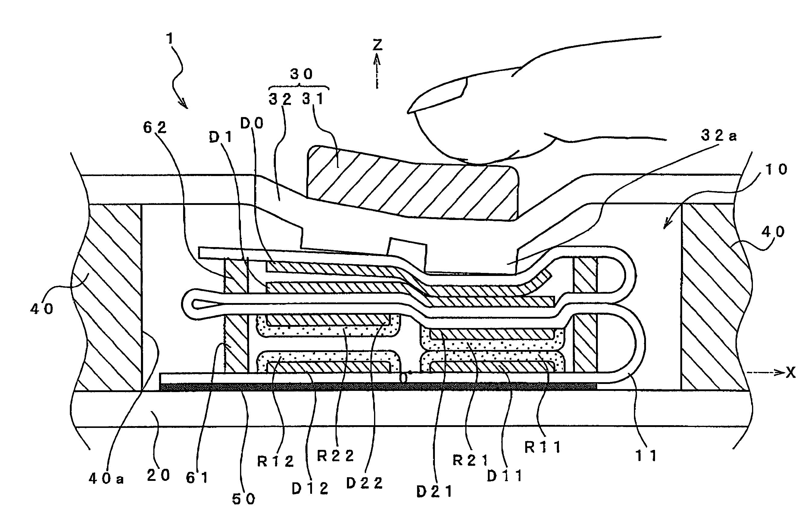
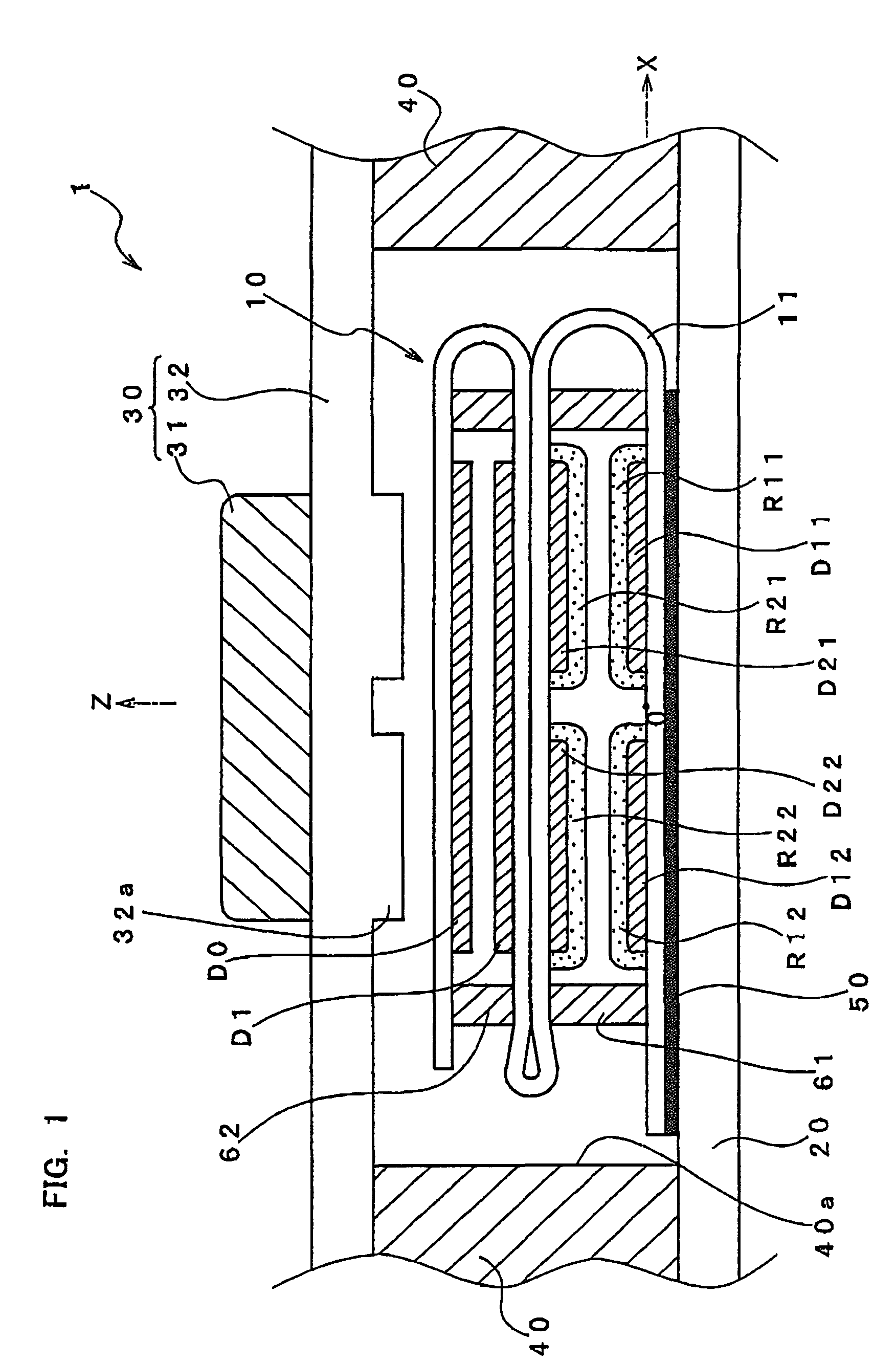
[0117]Now, the detailed structure of a resistance type sensor 101 will be described with reference to FIGS. 10 and 11. The resistance type sensor 101 of FIG. 10 differs from the resistance type sensor 1 of FIG. 1 in the construction of an operating portion 130 and the construction of displacement electrodes D101, D102 formed on the third surface 11c of the FPC 11. As the remaining constructions are the same as those of the resistance type sensor 1 of FIG. 1, the description thereon will be omitted, with like numerals given to like parts.

[0118]The operating portion 130 includes the operating button 31 and a keypad base 182 for supporting the operating button 131. The keypad base 132 has a circular protrusion 132a formed on a lower surface thereof at a position corresponding to the operating button 31 adhesive bonded to an upper surface of the keypad base. The protrusion 132a has an outer diameter substantially equal to an outer diameter of the operating button 31.

[0119]The displacem...

third embodiment

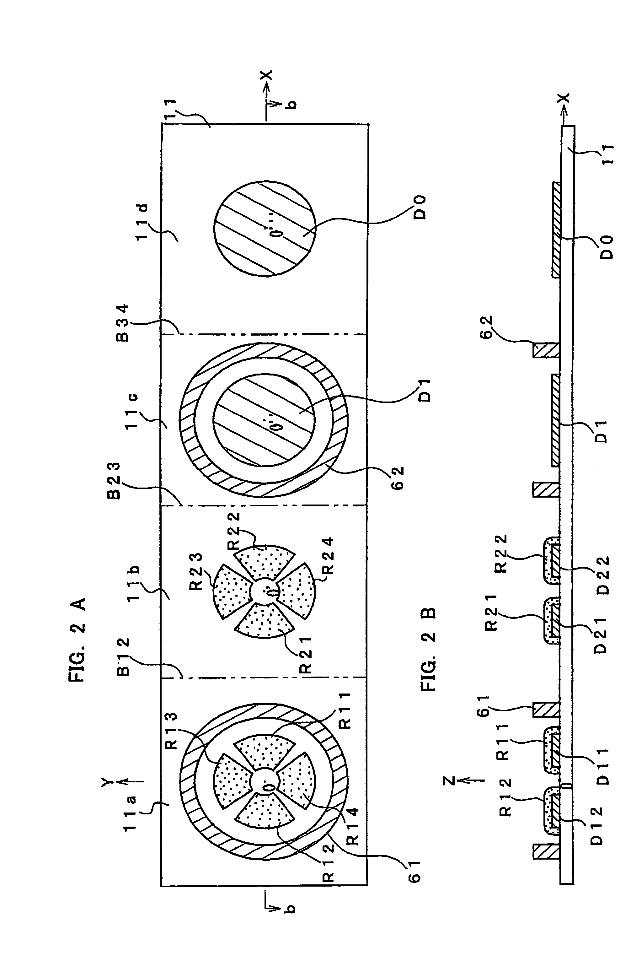
[0126]Now, the detailed structure of the resistance type sensor 201 will be described with reference to FIGS. 13 and 14. The resistance type sensor 201 of FIG. 13 differs from the resistance type sensor 1 of FIG. 1 in that whereas the resistance type sensor 1 is provided with a wakeup switch S1, the resistance type sensor 201 is provided with mere switches S201–S208. As the remaining constructions are the same as those of the resistance type sensor 1 of FIG. 1, the description thereon will be omitted, with like numerals given to like parts.

[0127]In the resistance type sensor 201, contact electrodes D211–D214 and D221–D224 and displacement electrodes D231–D234 are formed on the third surface 11c and the forth surface 11d of the FPC 11, respectively, in the screen printing using the conductive ink containing silver or carbon as raw material.

[0128]The contact electrodes D211–D214 and D-221–D224 are grouped in pairs and are arrayed adjacently so that the contact electrodes of each pair...


PUM


Abstract

In a resistance type sensor of the present invention, a sensor unit having variable contact resistances and a wakeup switch formed in two layers is produced by folding a FPC forming thereon pressure-sensitive resistive inks, a displacement electrode connected to ground, and a displacement electrode held at a power-supply voltage Vcc. Accordingly, whenever operation is applied to an operating button, the displacement electrode and the displacement electrode are reliably contacted with each other, first, and, then, resistance values of the variable contact resistances are changed while the displacement electrodes are kept in their contacted state. This enables the operation applied to the operating button to be detected reliably.

Description

BACKGROUND ON INVENTION[0001]1. Field of the Invention[0002]The present invention relates to a resistance type sensor suitably used for detecting a force applied from outside.[0003]2. Description of the Related Art[0004]A resistance type sensor is in general use as a device for converting magnitude and direction of a force applied by an operator into electric signal. For example, a device having the resistance type sensor for inputting operation of multidimensional direction incorporated as a so-called joystick is used as an input device of a mobile phone.[0005]A resistance type sensor can be used to input an operation having a specified dynamic range as a magnitude of a force applied by an operator. It is also used as a 2-dimensional or 3-dimensional sensor capable of dividing an applied force into dimensional components, for detection of the applied force.[0006]For example, Japanese Laid-open (Unexamined) Patent Publication No. Hei 6(1994)-347850 filed by the applicant of this app...

Claims


Application Information

Patent Timeline
IPC IPC(8): G01R27/00G01L1/20G01L5/16G06F1/32G06F3/033G06F3/0338G06F3/038
CPCG01L1/20G06F1/3215G06F1/3271G06F11/3093G06F11/3062G06F3/0338Y02B60/1257Y02D10/00
Inventor MORIMOTO, HIDEO
Owner NITTA CORP
Why Eureka
Try Eureka