Substrate for liquid crystal display device and liquid crystal display device

Inactive Publication Date: 2009-08-20
FUJIFILM CORP
View PDF8 Cites 3 Cited by
  • Summary
  • Abstract
  • Description
  • Claims
  • Application Information

AI Technical Summary

Benefits of technology

[0009]An object of the present invention is to provide a substrate for liquid crystal display device which can provide a vertically-aligned (VA)-mode liquid crystal display device having a good viewing angle d

Problems solved by technology

In addition, due to the characteristic of the optical compensation films that is likely to cause dimensional changes with environmental temperature or humidity, corner non-uniformity of LC

Method used


Image

  • Substrate for liquid crystal display device and liquid crystal display device
  • Substrate for liquid crystal display device and liquid crystal display device
  • Substrate for liquid crystal display device and liquid crystal display device

Examples


Example

Example 1

Preparation of Color Filter Substrate

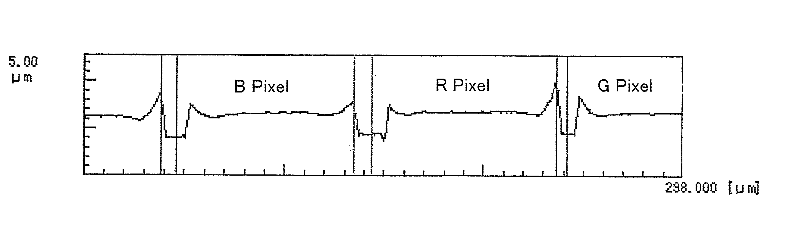
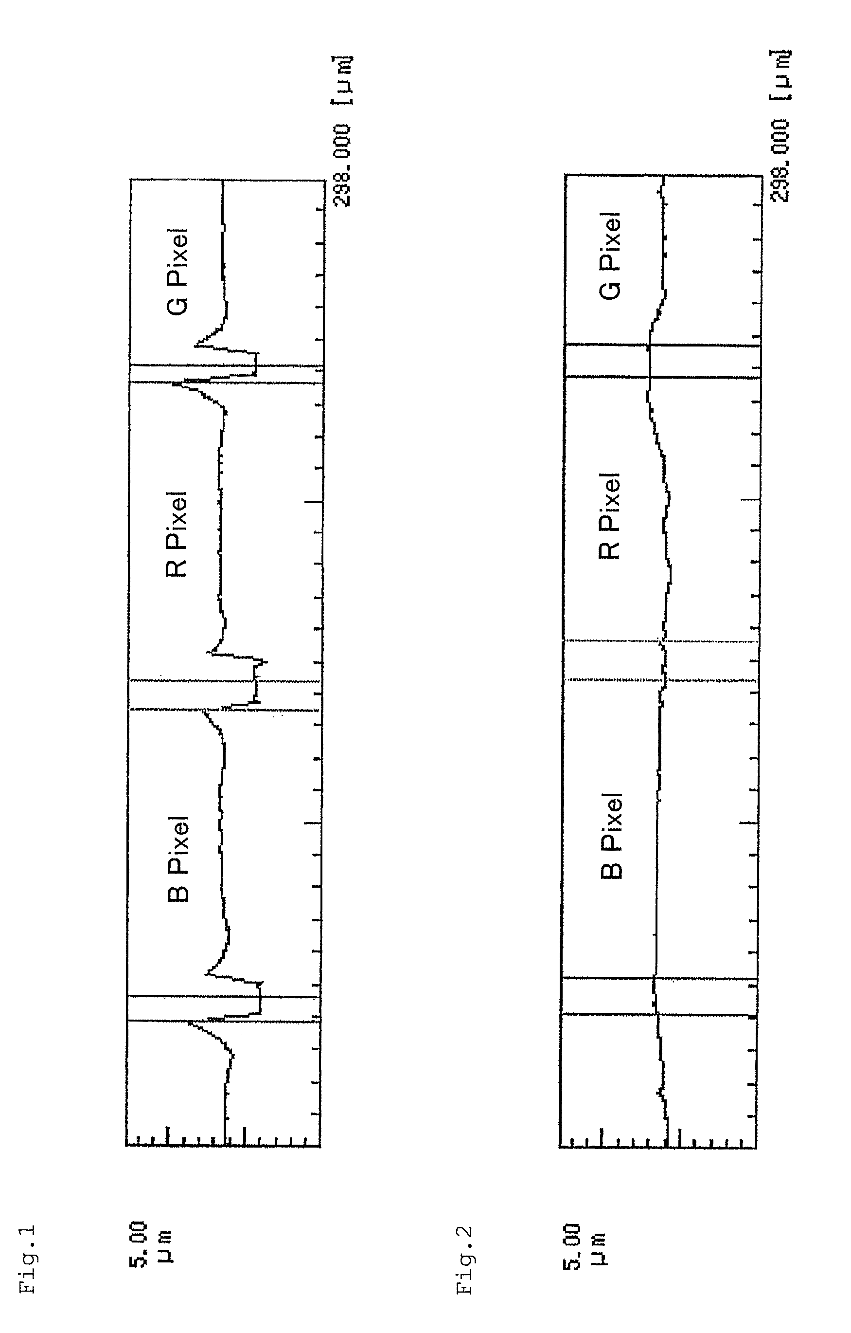
[0098]A color filter substrate having black matrix and color filters of RGB three-color on a glass substrate was prepared by using “transer” system described on page 25 of FUJIFILM RESEARCH & DEVELOPMENT No. 44 (1999). The obtained color filter substrate was subjected to a measurement of unevenness by using a laser microscope (product of KEYENCE Co., Ltd.). The result of the measurement of unevenness in FIG. 1 shows that unevenness of about 1.5 μm is present at the edge of each pixel.

[0099](Formation of the First Optically Anisotropic Layer)

[0100]The coating liquid for optically anisotropic layer, LC-1, was applied on the above color filter substrate by spin coating, heated and matured at 125° C. on the surface of the film for 3 minutes, to thereby obtain a layer of a uniform liquid crystal phase. The coated layer was then illuminated in the air atmosphere by ultraviolet radiation by using a 160 W / cm, air-cooled metal halide lamp (produc...

Example

Example 2

Preparation of Substrate 1 for Measurement of Retardation

[0105]For a measurement of the retardation of the optically anisotropic layer of the present invention, each optically anisotropic layer prepared in the same way as above except that the layers were prepared on a glass substrate instead of the color filter substrate was used.

[0106]A non-alkali glass substrate was cleaned using a rotating nylon-haired brush while spraying a glass cleaner solution conditioned at 25° C. by a shower for 20 seconds. After showered with purified water, the substrate was then heated in a substrate preheating heater at 100° C. for 2 minutes. Substrate 1 for measurement of retardation of Example 2 was prepared in the same manner as that of the formation of the first optically anisotropic layer of Example 1 on the above glass substrate.

Example

Example 3

[0107](Preparation of Substrate 2 for Measurement of Retardation)

[0108]An alignment layer was prepared in the same manner to that of Example 2 on a non-alkali glass substrate. The alignment layer was subjected to a rubbing treatment, and on the rubbed surface, Substrate 2 for measurement of retardation of Example 3 was prepared in the same manner as that of the formation of the second optically anisotropic layer of Example 1

[0109](Measurement of Retardation)

[0110]Frontal retardation at wavelength 550 nm, Re (O), and each of retardations Re (40) and Re (−40) wherein the sample is inclined by +40° and −40° using the slow axis as the axis of rotation were measured using a fiber-type spectrometer based on the parallel Nicol method. Results of the retardation measurements of Substrate 1 for measurement of retardation (Example 2) and Substrate 2 for measurement of retardation (Example 3) are shown in Table 1.

TABLE 1ReSample(0)Re (40)Re (−40)Substrate 1 for measurement0.032.231.6o...


PUM

PropertyMeasurementUnit
Percent by massaaaaaaaaaa

Abstract

A substrate for liquid crystal display device which can provide a vertically-aligned (VA)-mode liquid crystal display device having a good viewing angle dependence of contrast and at the same time can keep the production process as simple as possible is provided: a substrate for liquid crystal display device having a smoothing layer, the smoothing layer being a negative uniaxial optically anisotropic layer having an optical axis in the direction normal to the substrate surface, particularly the substrate for liquid crystal display device having a color filter layer and/or an electrode, and the negative uniaxial optically anisotropic layer having an optical axis in the direction normal to the substrate surface being directly provided on the color filter layer or the electrode.

Description

CROSS-REFERENCE TO RELATED APPLICATIONS[0001]This application claims benefit of priority under 35 USC 119 to Japanese Patent Application No. 2008-37518 filed on Feb. 19, 2008, the disclosure of which are each expressly incorporated by reference herein in its entirety.TECHNICAL FIELD[0002]The present invention relates to a substrate for liquid crystal display device and a liquid crystal display device. The present invention particularly relates a substrate for liquid crystal display device suitable for VA-mode liquid crystal display device.RELATED ART[0003]A CRT (cathode ray tube) has been mainly employed in various display devices used for office automation (OA) equipment such as a word processor, a notebook-sized personal computer and a personal computer monitor, mobile phone terminal and television set. In recent years, a liquid crystal display device (LCD) has more widely been used in place of a CRT, because of its thinness, lightweight and low power consumption. A liquid crystal...

Claims


Application Information

Patent Timeline
IPC IPC(8): G02F1/13363G02F1/1335
CPCG02F1/13363G02F1/133711G02F1/1393Y10T428/1041G02F2001/133635G02F2001/133742G02F2413/11G02F2001/133565C09K2323/031G02F1/133634G02F1/133565G02F1/133635G02F1/133742
Inventor NAKAJIMA, MASAOAMINORI, ICHIRO
Owner FUJIFILM CORP
Why Eureka
Try Eureka