Display control method and protective cover in electronic device

a technology of electronic devices and control methods, applied in static indicating devices, power supply for data processing, instruments, etc., can solve problems such as inconvenience for users, damage to protective covers, and user input may be disrupted by protective covers, so as to increase user convenience in using electronic devices and reduce battery power consumption.

Inactive Publication Date: 2016-04-21
SAMSUNG ELECTRONICS CO LTD
View PDF13 Cites 17 Cited by
  • Summary
  • Abstract
  • Description
  • Claims
  • Application Information

AI Technical Summary

Benefits of technology

[0013]Accordingly, another aspect of the present disclosure is to provide an input method and apparatus, such as a protective cover, capable of increasing user convenience in using an electronic device including the protective cover.
[0014]Accordingly, another aspect of the present disclosure is to provide an input method and apparatus, such as a protective cover, capable of reducing consumption of battery power in an electronic device including the protective cover.

Problems solved by technology

Since a portable electronic device is carried by a user, scratches may be generated on the outer surface or a Liquid Crystal Display (LCD) of the electronic device.
If a protective cover is used in an electronic device, input by a user may be disrupted by the protective cover.
However, since these functions represent just a subset of the multiple functions available in the electronic device, the protective cover may still inconvenience the user.
As another example, when the user performs any function using the electronic device while holding an object in one hand, the protective cover may cause the user considerable inconvenience.

Method used


Image

  • Display control method and protective cover in electronic device
  • Display control method and protective cover in electronic device
  • Display control method and protective cover in electronic device

Examples


Embodiment Construction

[0026]Hereinafter, the present disclosure will be described with reference to the accompanying drawings. The present disclosure may have various modifications and embodiments and thus will be described in detail with reference to specific embodiments illustrated in the drawings. However, it should be understood that there is no intent to limit the present disclosure to the particular forms disclosed and the present disclosure covers all modifications, equivalents, and / or alternatives falling within the spirit and scope of the disclosure. In connection with descriptions of the drawings, similar components are designated by the same reference numeral.

[0027]The expressions such as “include” and “may include” are used in the present o disclosure to refer to the presence of the disclosed functions, operations, and constituent elements and do not limit one or more additional functions, operations, and constituent elements. In the present disclosure, the terms s “include” and / or “have” ref...


PUM


Abstract

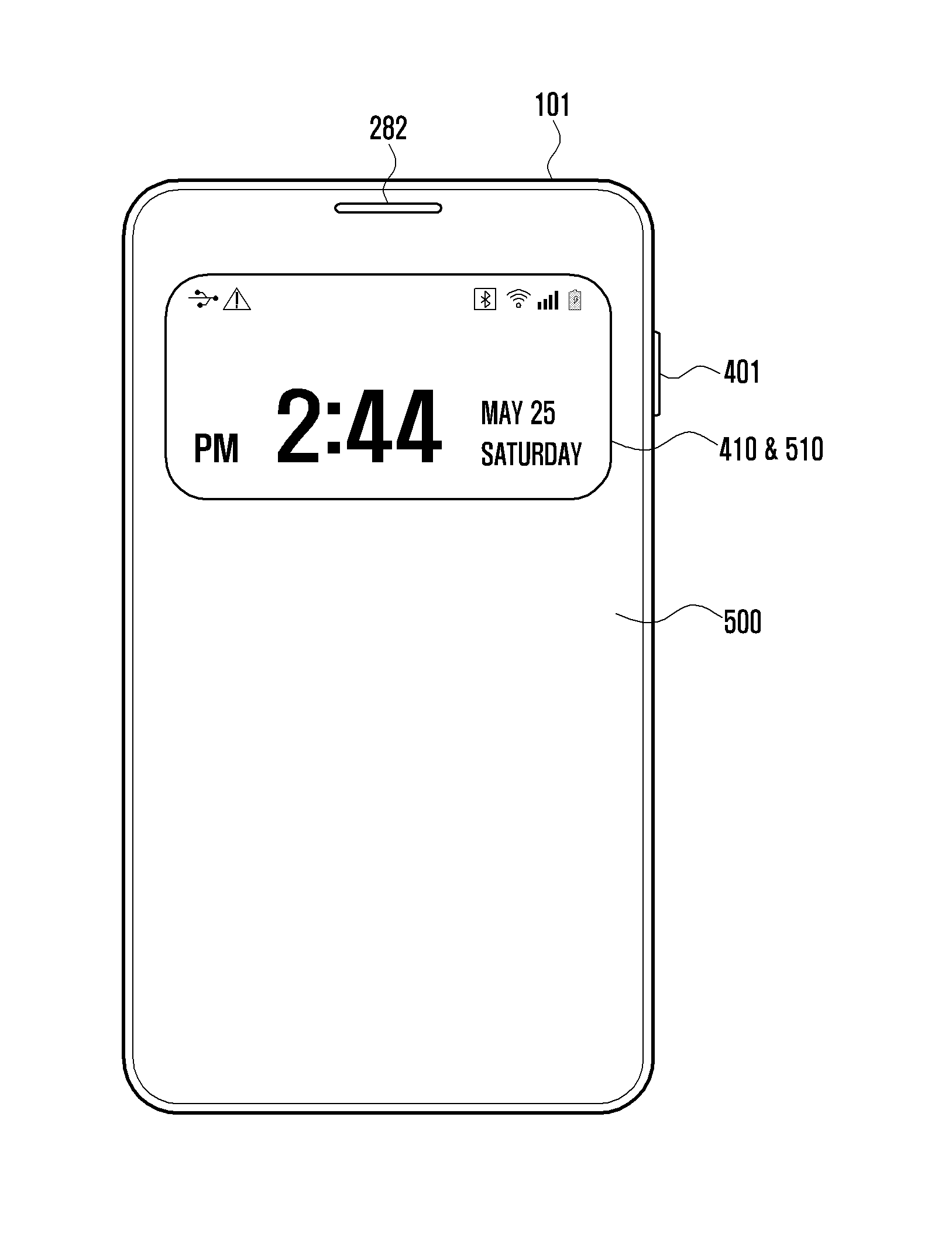
An input control method and an electronic device are provided. The electronic device includes a display, a memory for storing data, and a processor functionally connected to the display and the memory. The processor detects a first input, determines whether a cover for the electronic device is covered on the display when the first input is detected, wherein the cover includes a first visual region and a second visual region, and displays first data corresponding to the first input through at least one of a first region and a second region of the display when the cover covers the display, wherein the first region is arranged in a location corresponding to the first visual region and the second region is arranged in a location corresponding to the second visual region.

Description

PRIORITY[0001]This application claims priority under 35 U.S.C. §119(a) to a Korean Patent Application filed on Oct. 20, 2014, in the Korean Intellectual Property Office and assigned Serial No. 10-2014-0141468, the entire disclosure of which is incorporated herein by reference.BACKGROUND[0002]1. Field of the Disclosure[0003]The present disclosure relates generally to a display control method and apparatus in an electronic device, and more particularly to a display control method in an electronic device including a protective cover.[0004]2. Description of the Related Art[0005]Recently, as electronic technology has rapidly developed, portable electronic devices have become widespread. The portable electronic devices are being used in a variety of fields, including smartphones, tablet computers, electronic dictionaries, digital cameras, notebook computers, and MP3 players.[0006]Owing to advances in electronics, an input method of an electronic device has evolved into various forms. The ...

Claims


Application Information

Patent Timeline
Patent Type & Authority Applications(United States)
IPC IPC(8): G06F3/00H04B1/3888G06F1/32H04M1/7246
CPCG06F3/002H04B1/3888G06F1/3265G06F2200/1634H04M1/0214H04M1/0245H04M2250/22G06F3/0488G06F1/1626G06F1/1643G06F1/1677G06F1/3206Y02D10/00G06F3/0393H04M1/7246G06F3/01G06F3/147G06F3/041
Inventor LEE, BAEKDOOSAN
Owner SAMSUNG ELECTRONICS CO LTD
Why Eureka
Try Eureka