Beverage storage and dispensing apparatus

Inactive Publication Date: 2016-05-12
ORR TIMOTHY E
View PDF0 Cites 1 Cited by
  • Summary
  • Abstract
  • Description
  • Claims
  • Application Information

AI Technical Summary

Benefits of technology

The present invention is a beverage storage and dispensing apparatus that allows for efficient movement and processing of collapsible bags containing beverages. It can be operated by a single person and is capable of dispensing portable beverages in large quantities easily and quickly. Additionally, it eliminates the need for sanitizing and recycling of beverage containers, reduces the cost of handling potable liquids, and provides an efficient and durable solution.

Problems solved by technology

Rigid containers for the storage of beverages, although being traditionally acceptable, constitute a relatively expensive way to store and transport beverages.

Method used


Image

  • Beverage storage and dispensing apparatus
  • Beverage storage and dispensing apparatus
  • Beverage storage and dispensing apparatus

Examples


Embodiment Construction

[0032]Various aspects of the present invention will evolve from the following detailed description of the preferred embodiments thereof which should be referenced to the prior described drawings.

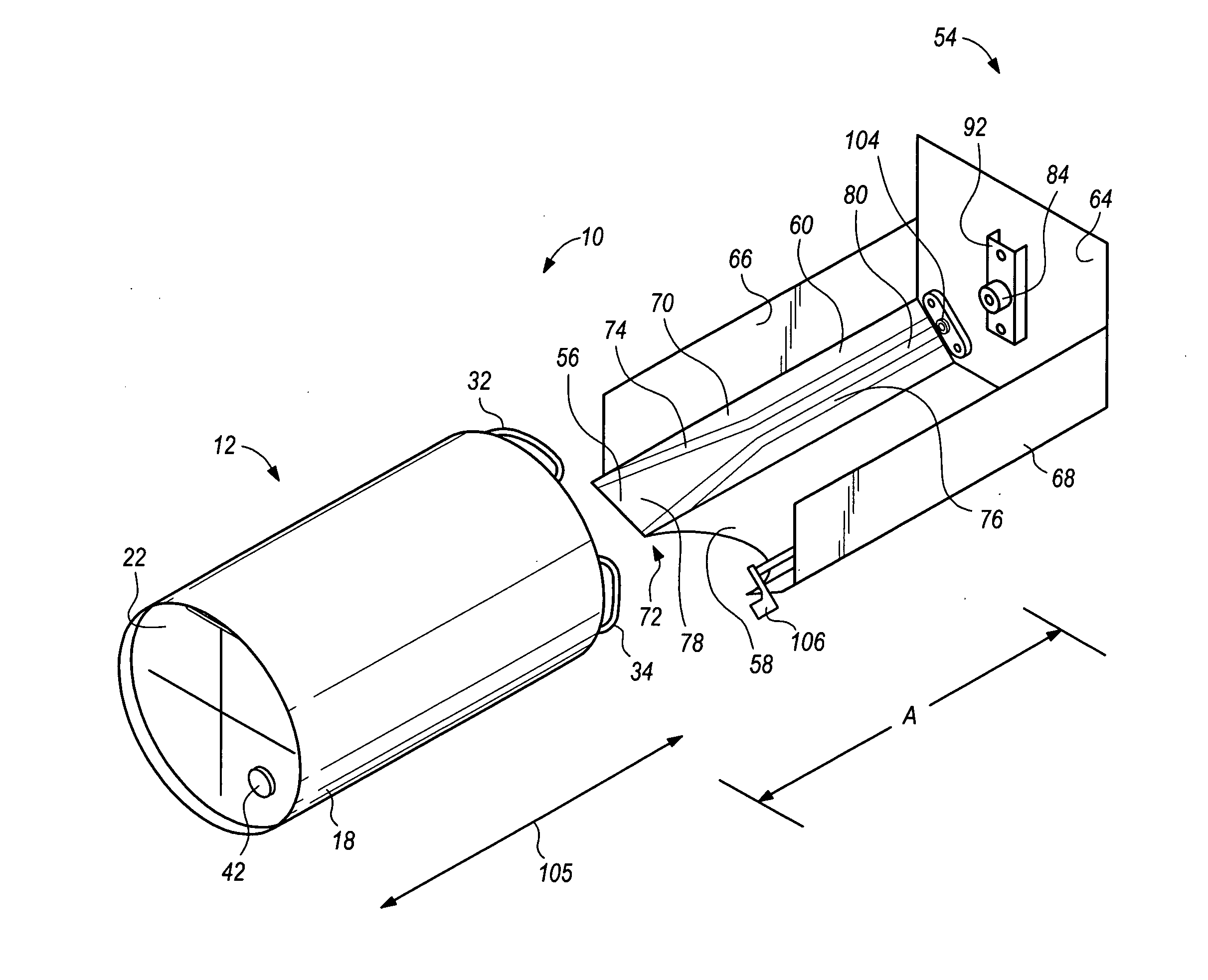
[0033]The apparatus for dispensing and storing beverages is depicted as whole by reference character 10, FIG. 8. Basically, the invention includes keg 12 and support 14 in sliding relationship. Each element will be discussed in detail as the specification continues.

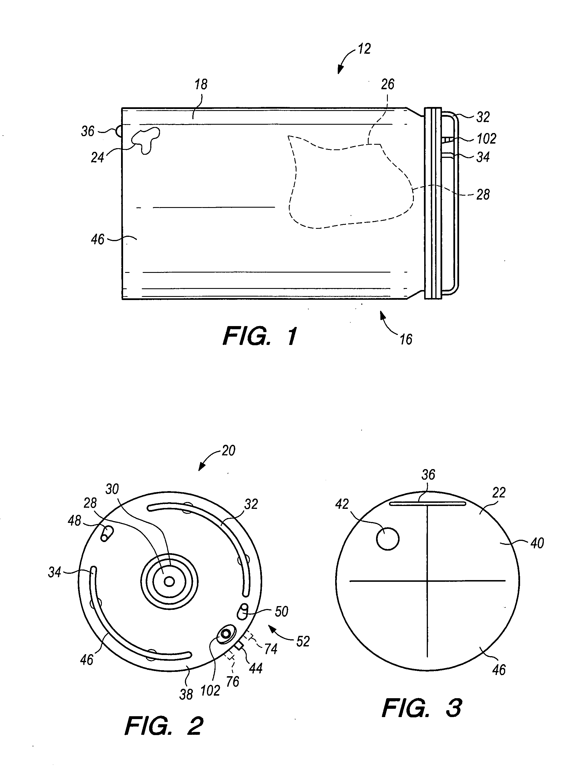
[0034]Keg 12, FIGS. 1-3 includes a housing 16 formed by a cylindrical body 18 and an end portion 20, FIG. 2. Keg 12 also includes end portion 22 generally opposite end portion 20 of body housing 16. Housing 16 possesses an interior chamber 24 (broken away portion on FIG. 1) which encompasses a collapsible bag 26 having a tap or outlet valve 28, shown partially in phantom on FIG. 1. Outlet valve 28, is also depicted in FIG. 2 as being accessible through an orifice 30 through an end portion 20. Again, such collapsible bag is fully d...


PUM


Abstract

A beverage container and dispenser utilizing a keg that slidingly engages a support to connect a liquid dispenser and compressed air inlet. The keg is guided into proper orientation in the support via a track located on the support.

Description

BACKGROUND OF THE INVENTION[0001]The present invention relates to a novel beverage storage and dispensing apparatus which is particularly useful for dispensing beverages stored in collapsible and flexible, valve operated bags.[0002]Beverages, such as wine and other spirits, are normally placed in rigid barrels or bottles and shipped to commercial distributors or consumers for consumption. Rigid containers for the storage of beverages, although being traditionally acceptable, constitute a relatively expensive way to store and transport beverages.[0003]In the last several years, portable beverages have been stored in flexible bags having a valve or tap to allow dispensing of the same. Such flexible bags have been placed in boxes formed of cardboard or polymeric materials. It has been found that packaging portable beverages in this manner is inexpensive compared to traditional rigid containers. Also, it has been realized, in the case of wine, that such wine is not oxidized by air when ...

Claims


Application Information

Patent Timeline
IPC IPC(8): B65D83/00B65D77/06
CPCB65D77/06B65D83/0055B67D1/0835B67D1/0891B67D2001/0822B67D2210/00097
Inventor ORR, TIMOTHY E.
Owner ORR TIMOTHY E
Why Eureka
Try Eureka