Positional tracking systems and methods

a positional tracking and positional technology, applied in the field of positional tracking, can solve the problems of increasing the weight of the hmd, increasing the amount of data sent from the camera to the computer and tracking latency, and the current tracking algorithm that rely on natural image features is typically not robust/precise enough to work consistently in many home environments

Active Publication Date: 2016-05-12
VALVE
View PDF2 Cites 70 Cited by
  • Summary
  • Abstract
  • Description
  • Claims
  • Application Information

AI Technical Summary

Problems solved by technology

This approach has several disadvantages, for example: it typically requires the VR user to greatly modify the appearance of his or her environment by covering all viewing directions with large tracking markers; it typically requires the user to perform a complex calibration step in order to the map the environment; and the tracking cameras attached to the HMD typically require a good lens for precise tracking, and this increases the weight of the HMD, typically significantly.
Since the tracking markers are typically complex in design in such implementations, their decoding is usually performed on the PC instead of an onboard processor in or near the HMD, and this typically increases the amount of data sent from the camera to the computer and the tracking latency.
Unfortunately, current tracking algorithms that rely on natural image features are typically not robust / precise enough to work consistently in many home environments, which often contain transparent, shiny, and / or textureless objects.
Extracting and identifying natural features from images also tends to be computationally expensive.

Method used


Image

  • Positional tracking systems and methods
  • Positional tracking systems and methods
  • Positional tracking systems and methods

Examples


Embodiment Construction

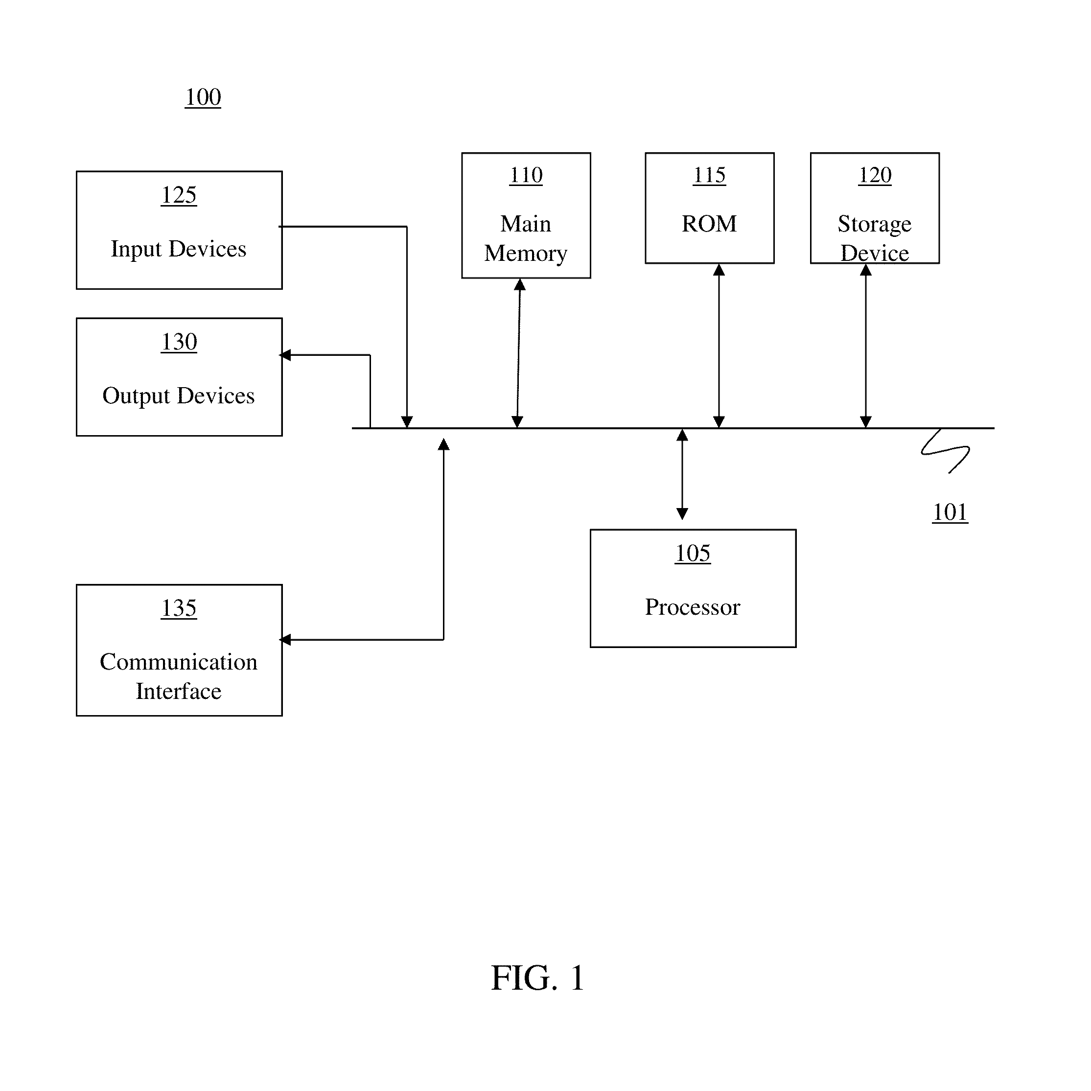
[0043]Those of ordinary skill in the art will realize that the following description of the present invention is illustrative only and not in any way limiting. Other embodiments of the invention will readily suggest themselves to such skilled persons, having the benefit of this disclosure, and the general principles defined herein may be applied to other embodiments and applications without departing from the spirit and scope of the present invention. Thus, the present invention is not intended to be limited to the embodiments shown, but is to be accorded the widest scope consistent with the principles and features disclosed herein. Reference will now be made in detail to specific implementations of the present invention as illustrated in the accompanying drawings. The same reference numbers will be used throughout the drawings and the following description to refer to the same or like parts.

[0044]The data structures and code described in this detailed description are typically stor...


PUM


Abstract

Optical positional tracking systems that may be used in virtual reality (VR) / augmented reality (AR) applications are described. Exemplary implementations comprise one or more receivers and one or more transmitters. Exemplary transmitters contains two orthogonal rotors that each emit a fan-shaped laser beam. Each beam is swept as the rotors are spun at constant speed. Exemplary optical receivers can be relatively small, and mounted at convenient locations on the VR display. These receivers consist of small optical detectors that may be mounted on head-mounted VR displays. Exemplary systems determine position by measuring the time at which each swept beam crosses each receiver / detector.

Description

CROSS-REFERENCE TO RELATED APPLICATIONS[0001]This application claims the benefit of Provisional Application Ser. Nos. 62 / 077,374, filed on Nov. 10, 2014, and 62 / 126,358, filed on Feb. 27, 2015, and the contents of both of those applications are herein incorporated by reference in their entirety.BACKGROUND OF THE DISCLOSURE[0002]1. Field of the Disclosure[0003]The disclosure relates generally to positional tracking, and more particularly to optics-based positional tracking systems and methods for virtual reality and / or augmented reality applications with improved features and characteristics.[0004]2. General Background[0005]Various positional tracking systems and methods are known in the art, varying in parameters such as tracking precision, tracking volume, tracking markers, manufacturing cost, and complexity of user setup. One current generation of desktop virtual reality (“VR”) experiences are created using head-mounted displays (“HMDs”), which can be tethered to a stationary comp...

Claims


Application Information

Patent Timeline
Patent Type & Authority Applications(United States)
IPC IPC(8): G01S17/58G01S17/42
CPCG01S17/42G01S17/58G01S7/4917G01S7/481G01S1/70G01S7/4814
Inventor YATES, ALANSELAN, JEREMY
Owner VALVE
Why Eureka
Try Eureka