Electrical connector and method of fabricating the same

a technology of electrical connectors and connectors, which is applied in the direction of one-pole connections, two-part coupling devices, coupling device connections, etc., can solve the problem of not being able to ensure the space in which the projecting terminal makes contact with the cylindrical terminal

Inactive Publication Date: 2016-05-12
DAIICHI SEIKO CO LTD
View PDF1 Cites 21 Cited by
  • Summary
  • Abstract
  • Description
  • Claims
  • Application Information

AI Technical Summary

Benefits of technology

[0043]The electric connector in accordance with the present invention is able to prevent molten resin for the insertion-molding process from flowing into an area at which the cylindrical hollow terminal and the projecting terminal make contact with each other while the inserting-molding process is being ca...

Problems solved by technology

For instance, if steps of arranging a cylindrical terminal in a cavity of a die and pouring molten resin into the cavity were merely carried out, the molten resin would flow...

Method used


Image

  • Electrical connector and method of fabricating the same
  • Electrical connector and method of fabricating the same
  • Electrical connector and method of fabricating the same

Examples


first embodiment

[0064]An electric connector in accordance with a first embodiment of the present invention is explained hereinbelow with reference to drawings.

[0065]In the specification, a wording “front” means a side through which the two electric connectors are fit into each other, and a wording “rear” means the opposite side.

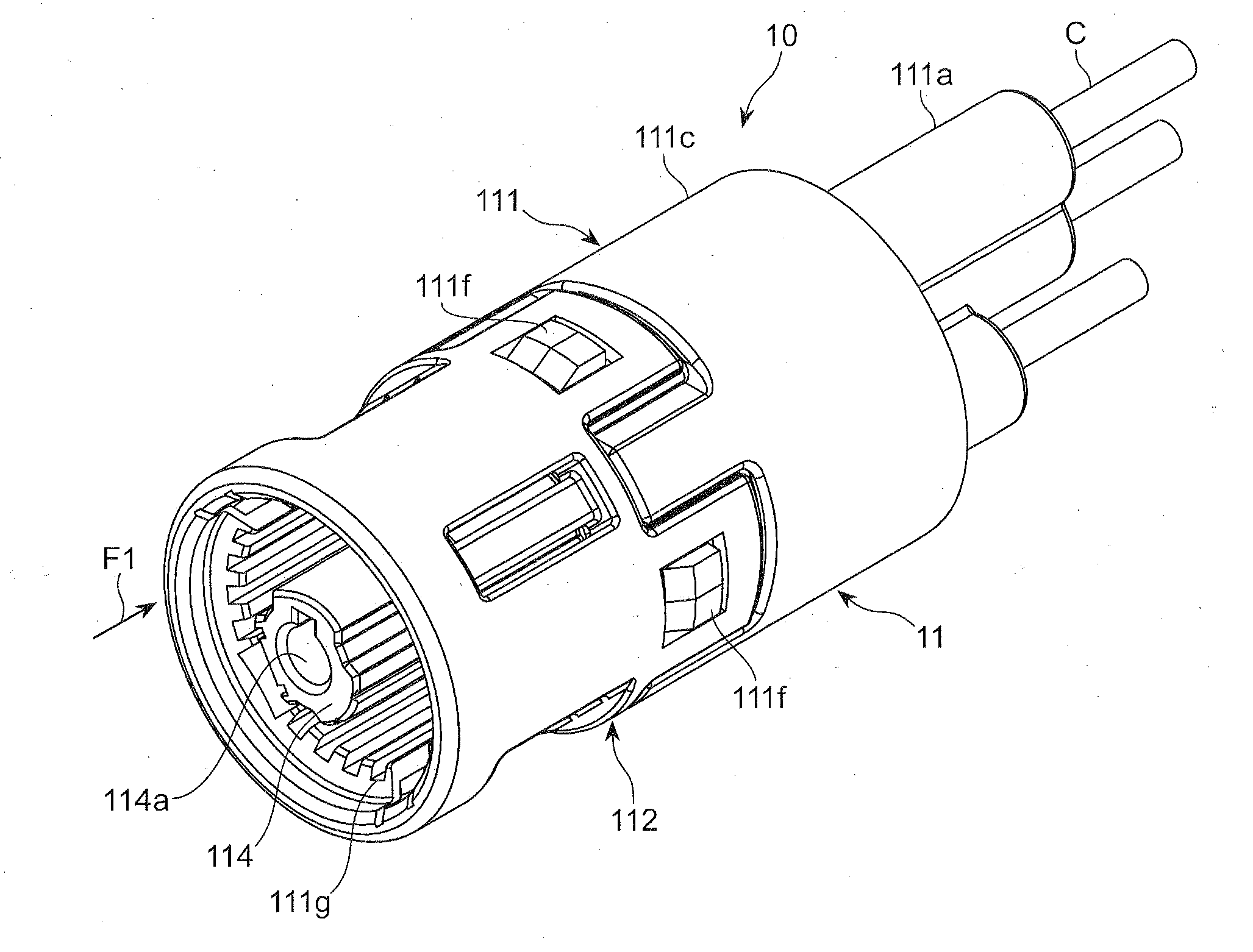
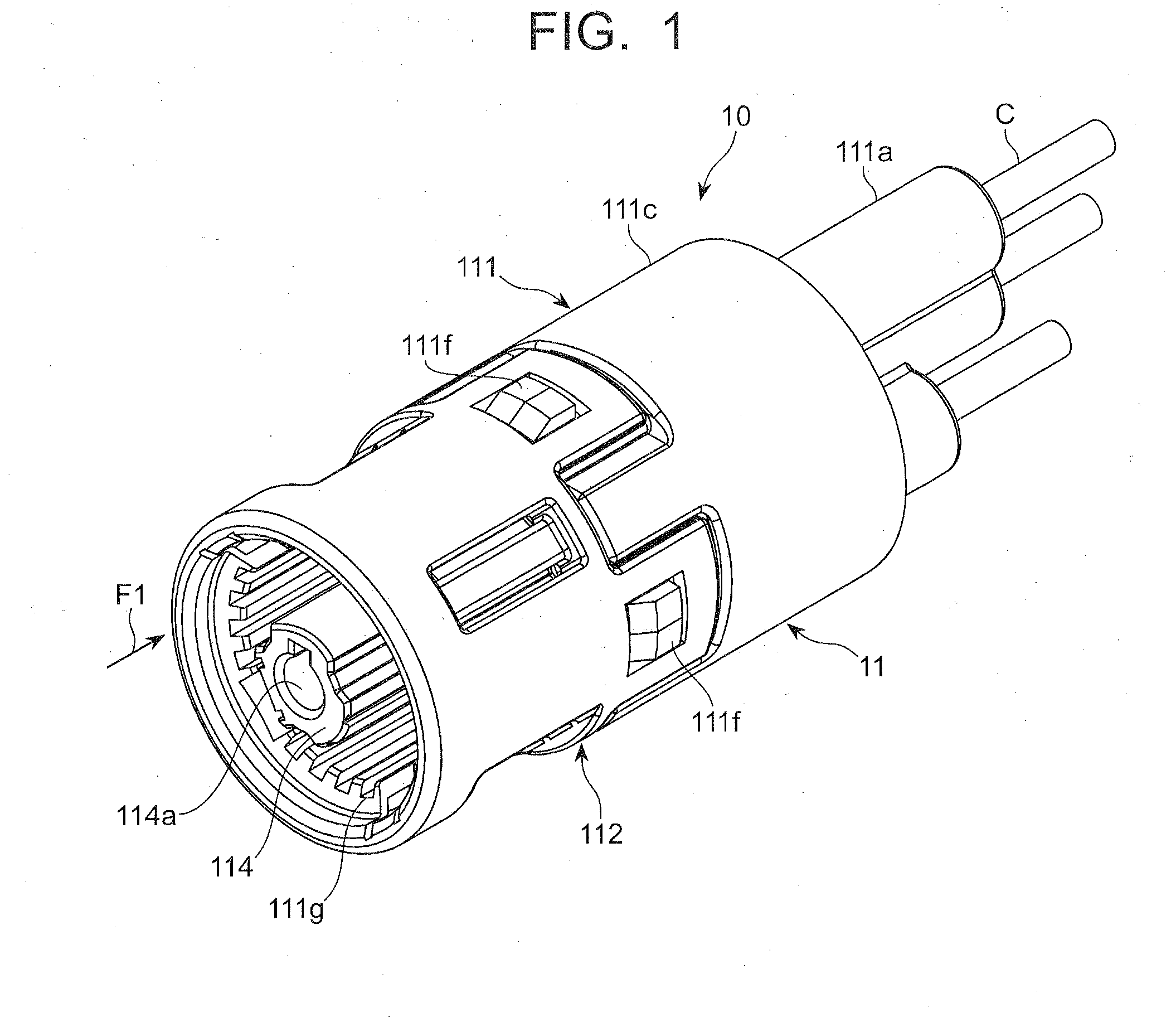
[0066]An electric connector 20 in accordance with the first embodiment of the present invention, illustrated in FIG. 6 is used together with a second electric connector 10 illustrated in FIG. 1 for connecting various connectors with a wire harness.

[0067]First, the second electric connector 10 is explained hereinbelow with reference to FIGS. 1 to 5.

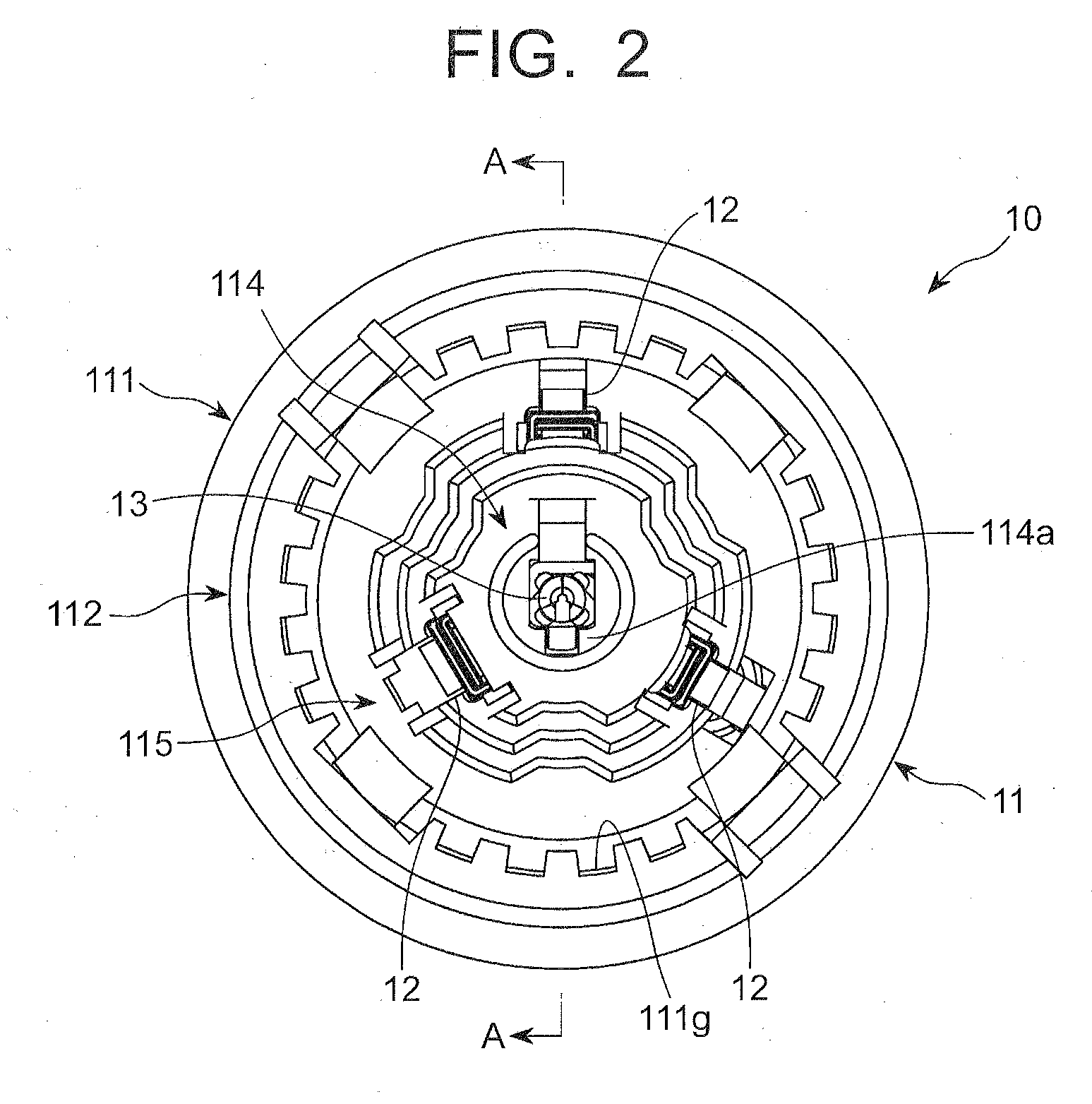
[0068]As illustrated in FIGS. 1 to 3, the second electric connector 10 includes an outer housing 11 into which the electric connector 20 is fit, a plurality of first contact terminals 12 through which the second electric connector 10 is electrically connected with the electric connector 20, and a projecting terminal 13.

[0069]The ou...

second embodiment

[0149]In the electric connector 20 in accordance with the first embodiment, the structure for preventing molten resin from flowing into an area at which the cylindrical terminal 23 and the projecting terminal 13 make contact with each other while an inserting-molding process is being carried out is comprised of the annular projections 231a. In the electric connector in accordance with the second embodiment, the structure is comprised of a closed section comprising a closed proximal end of the cylindrical terminal 23 in place of the above-mentioned annular projections 231a.

[0150]Parts or elements that correspond to those of the first embodiment have been provided with the same reference numerals, and operate in the same manner as corresponding parts or elements in the first embodiment, unless explicitly explained hereinbelow.

[0151]As illustrated in FIGS. 15 to 17, a cylindrical terminal 23x is housed in the second shaft 213 of the inner housing 21, similarly to the cylindrical termi...


PUM

PropertyMeasurementUnit
Lengthaaaaaaaaaa
Thicknessaaaaaaaaaa
Diameteraaaaaaaaaa

Abstract

The electric connector includes a housing to be fit into a second electric connector, and a cylindrical hollow terminal making contact with a projecting terminal arranged in the second electric connector when the projecting terminal is inserted into the cylindrical hollow terminal, the housing and the cylindrical hollow terminal being formed integrally with each other by an insertion-molding process, the cylindrical hollow terminal being formed with a structure for preventing molten resin from flowing into an area at which the cylindrical hollow terminal and the projecting terminal make contact with each other while the inserting-molding process is being carried out.

Description

BACKGROUND OF THE INVENTION[0001]1. Field of the Invention[0002]The invention relates to an electric connector including a housing to be fit into a second electric connector, and a cylindrical hollow terminal making contact with a projecting terminal arranged in the second electric connector when the projecting terminal is inserted into the cylindrical hollow terminal. The invention further relates to a method of fabricating the electric connector.[0003]2. Description of the Related Art[0004]There is known an electric connector including a cylindrical connector. The electric connector makes an electrical connection with a second electric connector including a projecting terminal when the projecting terminal is fit into the cylindrical connector of the electric connector.[0005]Even if the electric connector and the second electric connector are fit into each other with the electric connector or the second electric connecter is in rotation around an axis thereof, it is possible to cau...

Claims


Application Information

Patent Timeline
IPC IPC(8): H01R24/38H01R9/05H01R43/16
CPCH01R24/38H01R43/16H01R9/05H01R2101/00
Inventor ENDO, TAKAYOSHITOUNO, SHUJI
Owner DAIICHI SEIKO CO LTD
Why Eureka
Try Eureka