Pipe machining apparatuses and methods of operating the same

a technology of pipe cutting and pipe, which is applied in the direction of manufacturing tools, portable lathes, tube shearing machines, etc., can solve the problems of pipe cutting apparatuses that are difficult to assemble and manipulate, pipe cutting apparatuses that are difficult to position around pipes, and tool carriers that may unfavorably slide off of frame sections

Active Publication Date: 2016-05-19
ILLINOIS TOOL WORKS INC
View PDF10 Cites 12 Cited by
  • Summary
  • Abstract
  • Description
  • Claims
  • Application Information

AI Technical Summary

Benefits of technology

The present invention provides a pipe machining apparatus that includes a frame and a tool carrier that moves relative to the frame and the pipe. The apparatus also includes a hinge that allows the first and second sections to move relative to each other. A support member is also provided with a coupling member that engages the apparatus, a body that extends from the coupling member, and a pad that engages a surface for support. Additionally, the invention provides a method for lifting the pipe machining apparatus using a lifting mechanism. The technical effects of the invention are improved efficiency and flexibility in pipe machining, reduced labor intensity, and improved safety during operation.

Problems solved by technology

Existing pipe cutting apparatuses may be large in size, heavy, and contain multiple components, thereby making it difficult to assemble and manipulate the pipe cutting apparatus.
Moreover, such pipe cutting apparatuses may be difficult to position around a pipe.
Furthermore, due to the roller bearings between the tool carrier and the frame of pipe machining apparatuses, the tool carrier may move relative to the frame during assembly and set up of pipe machining apparatuses.
Prior to assembly of the sections or halves of the pipe machining apparatus, the sections of pipe machining apparatus have open ends and the sections of the tool carrier may undesirably slide off of the frame sections.
Additionally, split frame pipe machining apparatuses are limited in the manners that they can couple to pipes.
The components utilized to couple the pipe machining apparatuses to pipes have limitations that do not provide a wide variety of functionality.
Such bearings undergo significant stresses and oftentimes prematurely wear due to improper lubrication.

Method used


Image

  • Pipe machining apparatuses and methods of operating the same
  • Pipe machining apparatuses and methods of operating the same
  • Pipe machining apparatuses and methods of operating the same

Examples


Embodiment Construction

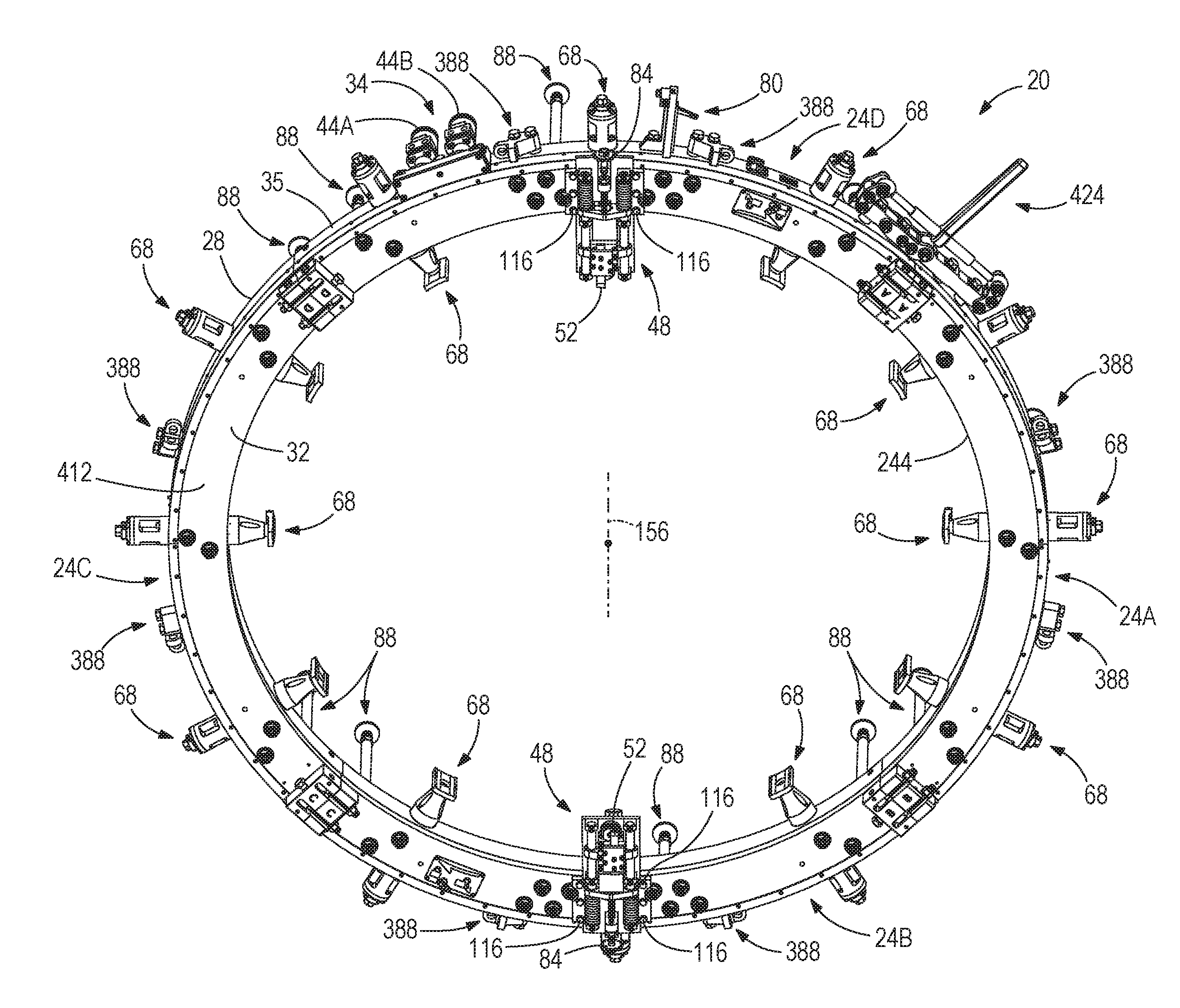
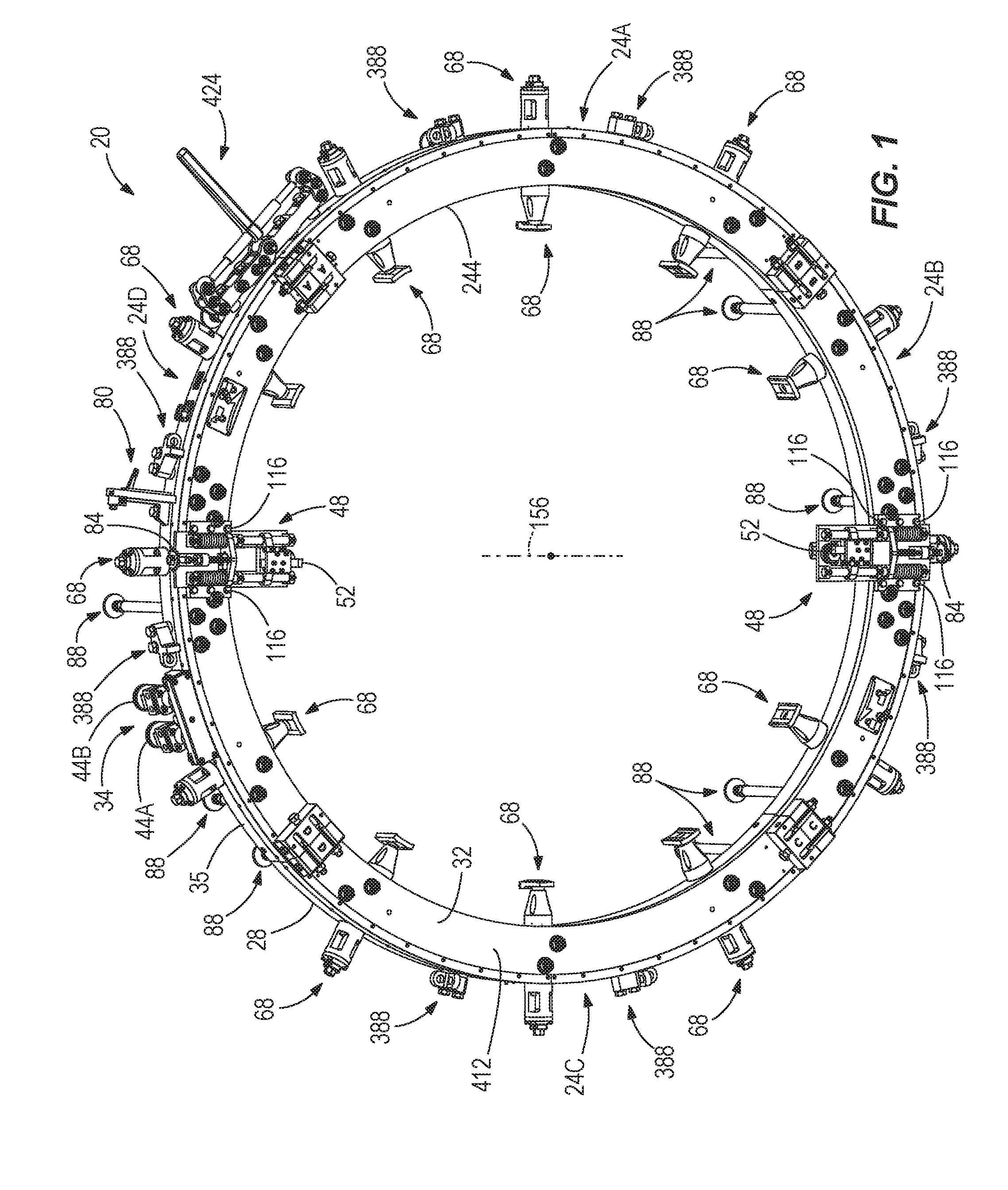
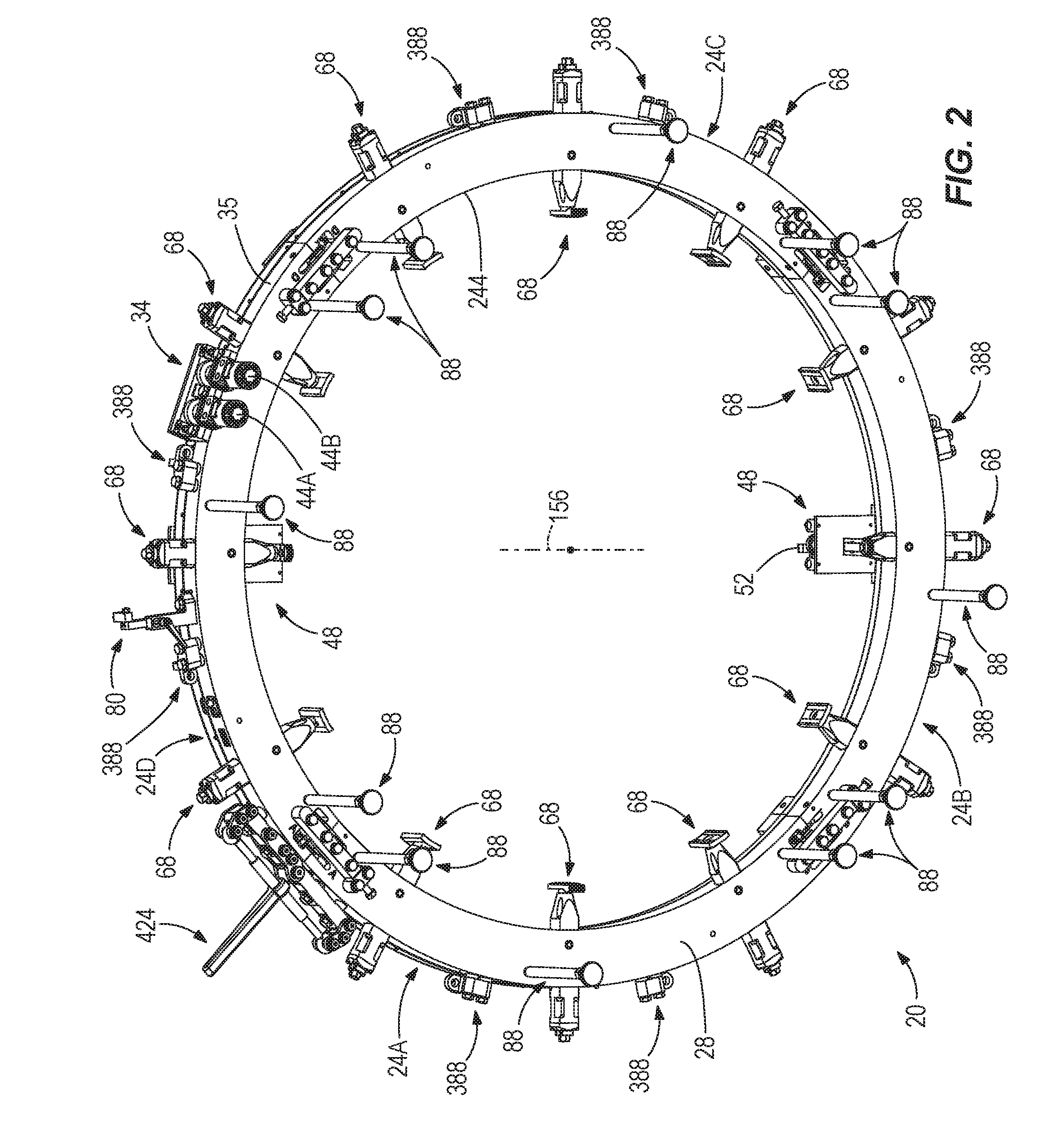
[0045]With reference to FIGS. 1-3, an exemplary embodiment of a pipe machining apparatus 20 adapted to machine pipes of varying diameters is illustrated. In some exemplary embodiments, the apparatus 20 completely cuts through pipes. In other exemplary embodiments, the apparatus 20 prepares an end of a pipe for coupling to another pipe. In still other exemplary embodiments, the apparatus 20 both completely cuts and prepares a pipe for coupling to another pipe. The apparatus 20 is adapted to cut pipes of a variety of different diameters such as, for example, about 60 inches, about 75 inches, about 90 inches, about 105 inches, about 120 inches, less than 60 inches, greater than 120 inches, or any other pipe diameter.

[0046]In the illustrated exemplary embodiment, pipe machining apparatus 20 is formed of four joined-together sections 24A, 24B, 24C, 24D and includes a frame 28 and a tool carrier 32. A portion of the frame28 and the tool carrier 32 are included in each section 24A, 24B, 24...


PUM


Abstract

Pipe machining apparatuses are provided. In some aspects, a pipe machining apparatus may include a hinge to allow two sections of the pipe machining apparatus to move relative to one another. In another aspect, a support member may be provided to support a pipe machining apparatus on a surface. In a further aspect, a support member may be provided that allows lifting of a pipe machining apparatus in either a horizontal position or a vertical position.

Description

RELATED APPLICATIONS[0001]The present application is a divisional of co-pending U.S. Non-Provisional patent application Ser. No. 13 / 798,782, filed Mar. 13, 2013, which claims the priority benefit of U.S. Provisional Patent Application No. 61 / 750,445, filed Jan. 9, 2013, all of which are incorporated by reference herein in their entirety.FIELD OF THE INVENTION[0002]The present disclosure generally relates to pipe machining apparatuses and, more particularly, to split frame pipe machining apparatuses for machining large diameter pipes.BACKGROUND[0003]A variety of different types of pipe machining apparatuses exist to perform various machining processes on pipes. One such process includes cutting pipes. Large diameter pipes may be cut with a split frame pipe machining apparatus, which includes two frame halves that surround the pipe from respective sides and are coupled together around the pipe. Such a pipe cutter includes a tool or cutting device that encircles the pipe and moves towa...

Claims


Application Information

Patent Timeline
Patent Type & Authority Applications(United States)
IPC IPC(8): B23D21/04B23Q9/02B23Q9/00B23B5/14B23B5/08
CPCB23D21/04B23B5/14B23B2215/72B23Q9/0021B23Q9/02B23B5/08B23B3/26B23Q9/0057B26D3/16B26D7/00Y10T82/16442Y10T82/22Y10T82/2522Y10T82/30B26D7/2614
Inventor PIERCE, KENNETH R.GEARHART, MICHAEL W.
Owner ILLINOIS TOOL WORKS INC
Why Eureka
Try Eureka