
Premix fuel nozzle assembly

a fuel nozzle and premix technology, applied in the direction of combustion types, transportation and packaging, lighting and heating apparatus, etc., can solve the problems of affecting the performance of the combustor, reducing the stability of the pilot, and not having liquid fuel available and/or cost effective,

Active Publication Date: 2016-05-26
GENERAL ELECTRIC CO
View PDF8 Cites 26 Cited by
  • Summary
  • Abstract
  • Description
  • Claims
  • Application Information

AI Technical Summary

Benefits of technology

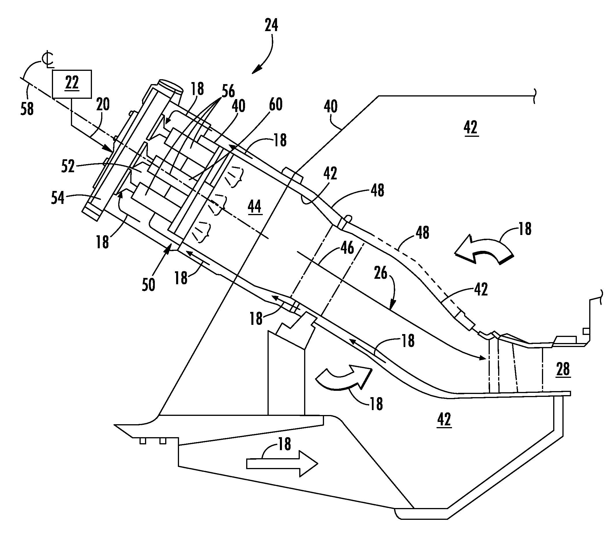
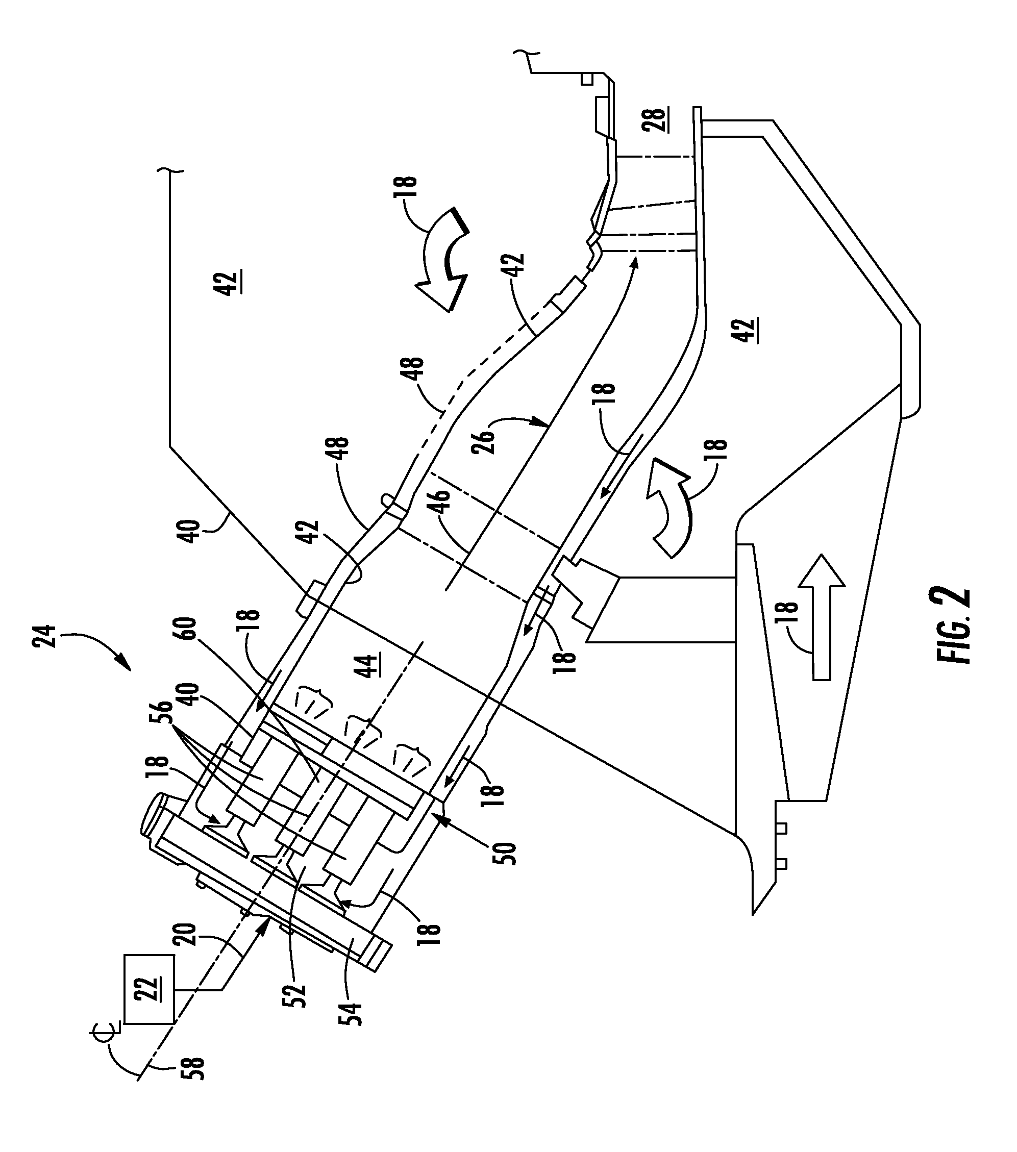
The invention is a premix fuel nozzle assembly and a combustor with the assembly. The premix fuel nozzle assembly includes a center body, a pilot premix fuel nozzle assembly, and a premix tip with premix tubes and fuel ports. The assembly also has a purge air cartridge assembly with a feed tube and tip portion that define a purge air passage. The purge air cartridge assembly includes an aft wall that extends at least partially through an opening defined by the premix tip and has a single axially extending orifice that is in fluid communication with the purge air passage. The technical effects of the invention are improved combustion efficiency, reduced emissions, increased power output, and improved performance and reliability of the combustor.

Problems solved by technology

Typically, the combustor will operate on gaseous fuel, however, the liquid fuel may be used as a backup or alternative fuel in the event the gaseous fuel becomes unavailable or supply is limited.
Although a gas turbine may include combustors that have “Dual Fuel” or backup fuel capability, it may not be required by the operator or in some cases the liquid fuel may not be available and / or may not be cost effective.
As a result, the purge air may decrease the stability of the pilot flame which may impact the performance of the combustor.

Method used


Image

  • Premix fuel nozzle assembly
  • Premix fuel nozzle assembly
  • Premix fuel nozzle assembly

Examples


Embodiment Construction

[0025]Reference will now be made in detail to present embodiments of the invention, one or more examples of which are illustrated in the accompanying drawings. The detailed description uses numerical and letter designations to refer to features in the drawings. Like or similar designations in the drawings and description have been used to refer to like or similar parts of the invention. As used herein, the terms “first”, “second”, and “third” may be used interchangeably to distinguish one component from another and are not intended to signify location or importance of the individual components. The terms “upstream” and “downstream” refer to the relative direction with respect to fluid flow in a fluid pathway. For example, “upstream” refers to the direction from which the fluid flows, and “downstream” refers to the direction to which the fluid flows.

[0026]Each example is provided by way of explanation of the invention, not limitation of the invention. In fact, it will be apparent to ...


PUM

PropertyMeasurementUnit
combustionaaaaaaaaaa
temperaturesaaaaaaaaaa
stabilityaaaaaaaaaa

Abstract

A premix fuel nozzle assembly includes a center body, a pilot premix fuel nozzle assembly that extends axially through the center body and that includes a premix tip having a plurality of premix tubes that each defines a premix passage and a fuel port. The premix passage of each premix tube is in fluid communication with the pilot air passage. The premix fuel nozzle assembly further includes a purge air cartridge assembly that extends axially within the pilot air passage. The purge air cartridge assembly includes a feed tube portion and a tip portion that define a purge air passage within the pilot air passage. The tip portion comprises an aft wall that extends at least partially through an opening defined by the premix tip. The aft wall includes a single axially extending orifice that is in fluid communication with the purge air passage.

Description

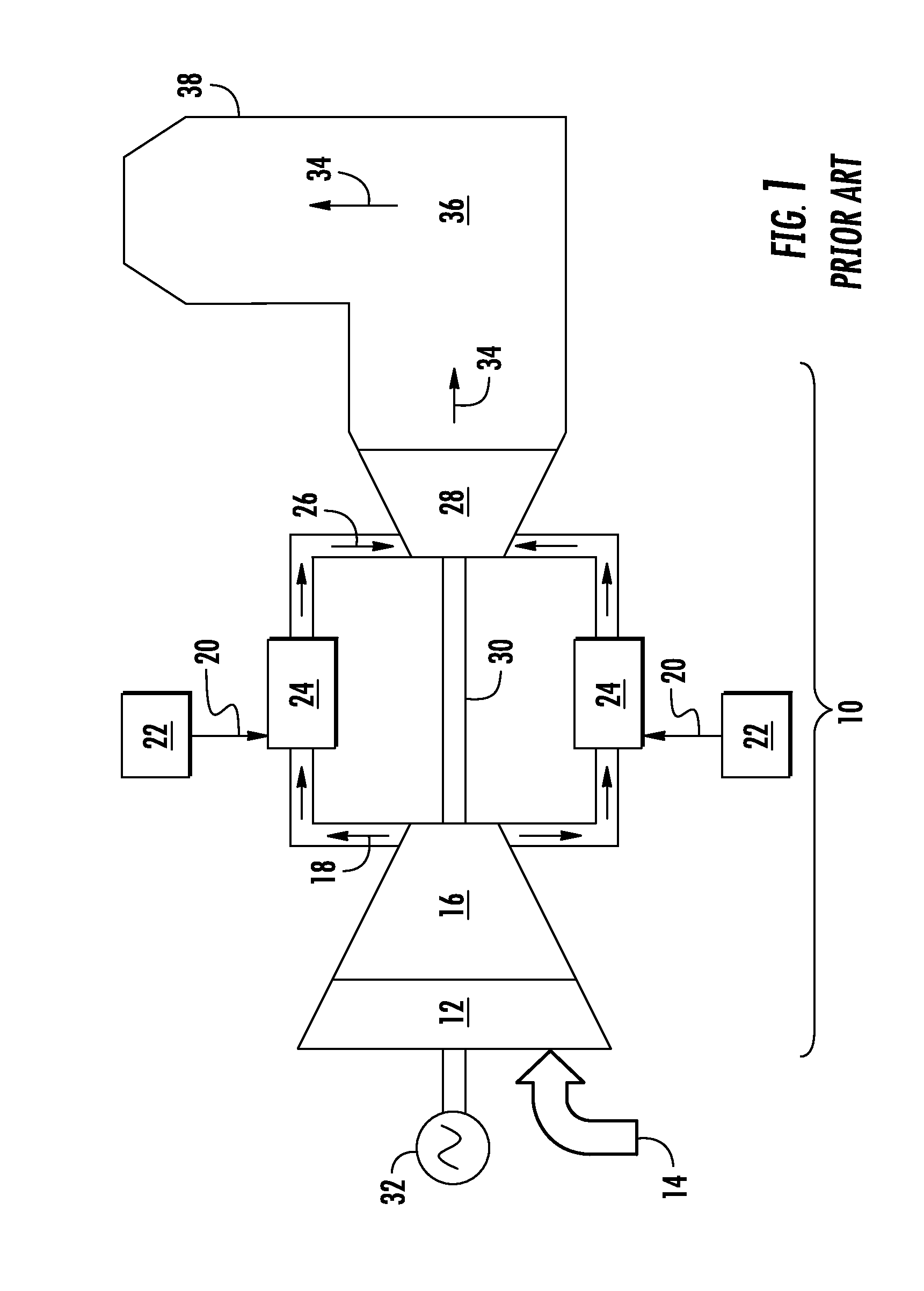
FIELD OF THE INVENTION[0001]The present invention generally involves a premix fuel nozzle assembly for a gas turbine combustor. More specifically, the invention relates to a dual fuel premix fuel nozzle assembly that is configured for gas only operation.BACKGROUND OF THE INVENTION[0002]Gas turbine combustors for power generation are generally available with fuel nozzles configured for either “Dual Fuel” operation or for “Gas only” operation. “Gas Only” refers to a fuel nozzle that is restricted to providing a gaseous fuel such as natural gas for combustion in a combustion chamber of the combustor. “Dual Fuel” refers to a fuel nozzle that may be configured to provide either a liquid fuel or a gaseous fuel for combustion during operation of the combustor. Typically, the combustor will operate on gaseous fuel, however, the liquid fuel may be used as a backup or alternative fuel in the event the gaseous fuel becomes unavailable or supply is limited. In certain configurations, a gas turb...

Claims


Application Information

Patent Timeline
Patent Type & Authority Applications(United States)
IPC IPC(8): F23D17/00B01F5/04F23K5/14F23D14/58F23K5/00B01F3/02F23D11/38B01F23/10
CPCF23D17/002B01F3/02B01F5/0415F23D11/383F23D14/58F23K5/007F23K5/14B01F2005/0438B01F2215/0085F23D2209/30F23R3/28F23R3/343F23R3/36F23R2900/03343F23R3/14F23R3/286F23D17/00F23K5/18F23R3/283
Inventor STEWART, JASON THURMANGIBSON, MICHAEL CHRISTOPHERROMIG, BRYAN WESLEY
Owner GENERAL ELECTRIC CO
Learn More