Car emergency system and method of emergency measures using the car emergency system

a car emergency and emergency system technology, applied in the field of car emergency, can solve the problems of damage or human life, procedures and costs to determine the cause of the accident, and to deal with the aftermath, and may become complicated, and the procedures and costs may be difficult to determin

Active Publication Date: 2016-05-26
HYUNDAI MOTOR CO LTD
View PDF3 Cites 3 Cited by
  • Summary
  • Abstract
  • Description
  • Claims
  • Application Information

AI Technical Summary

Benefits of technology

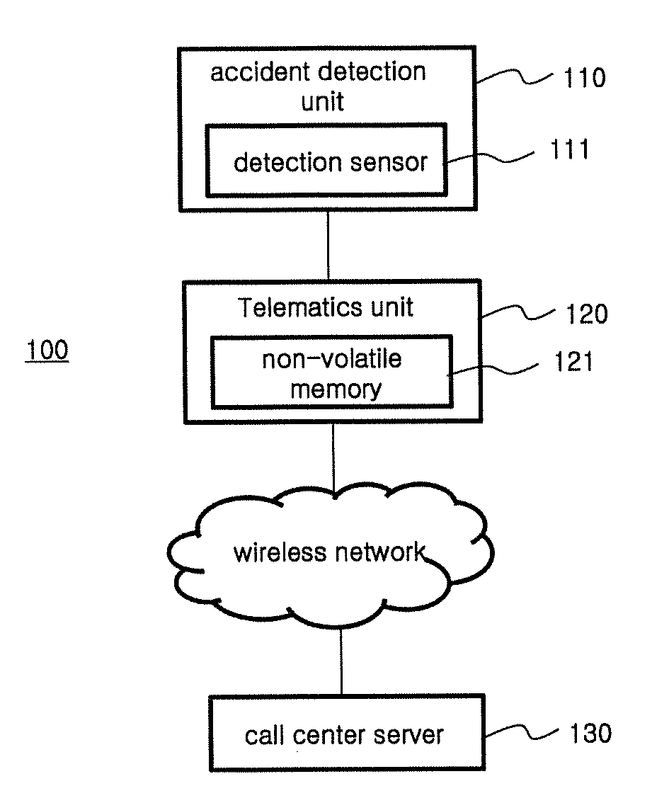
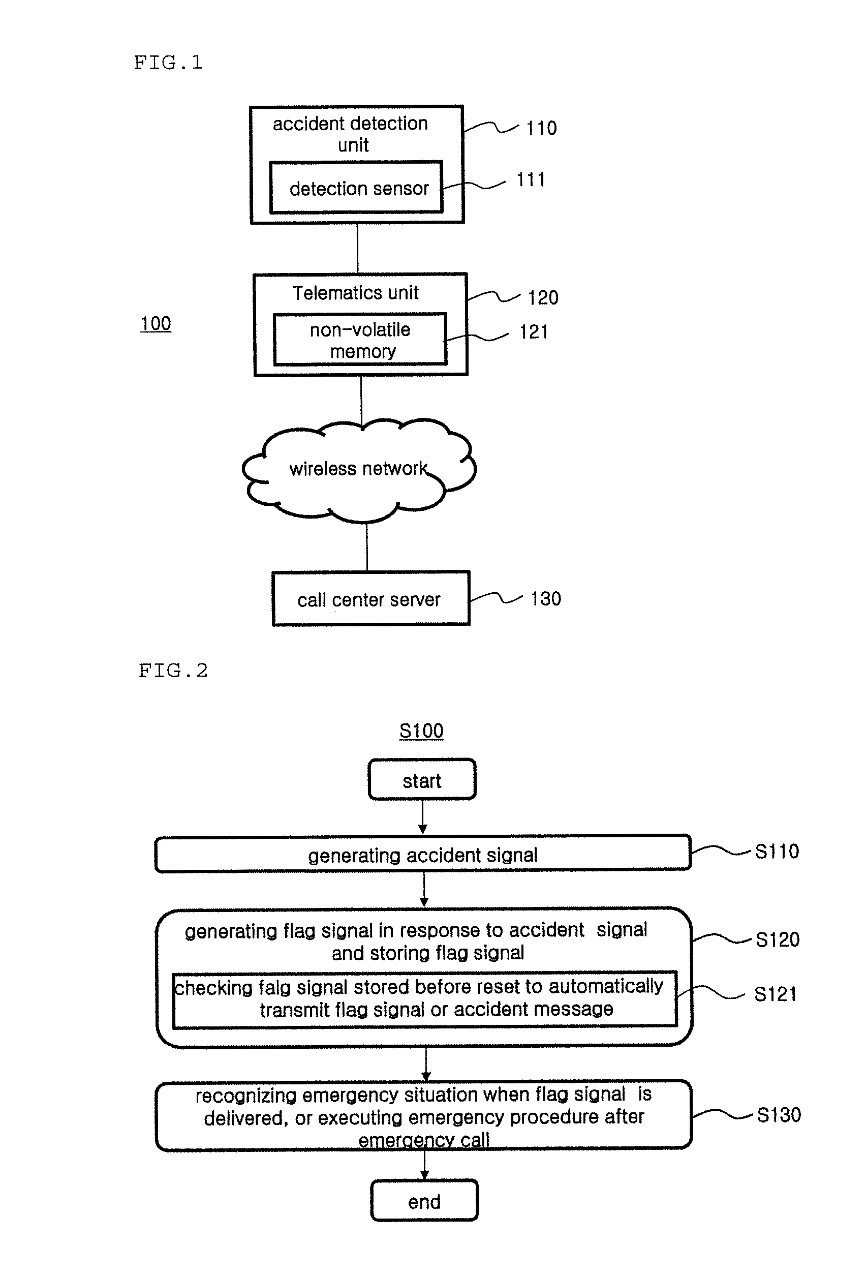
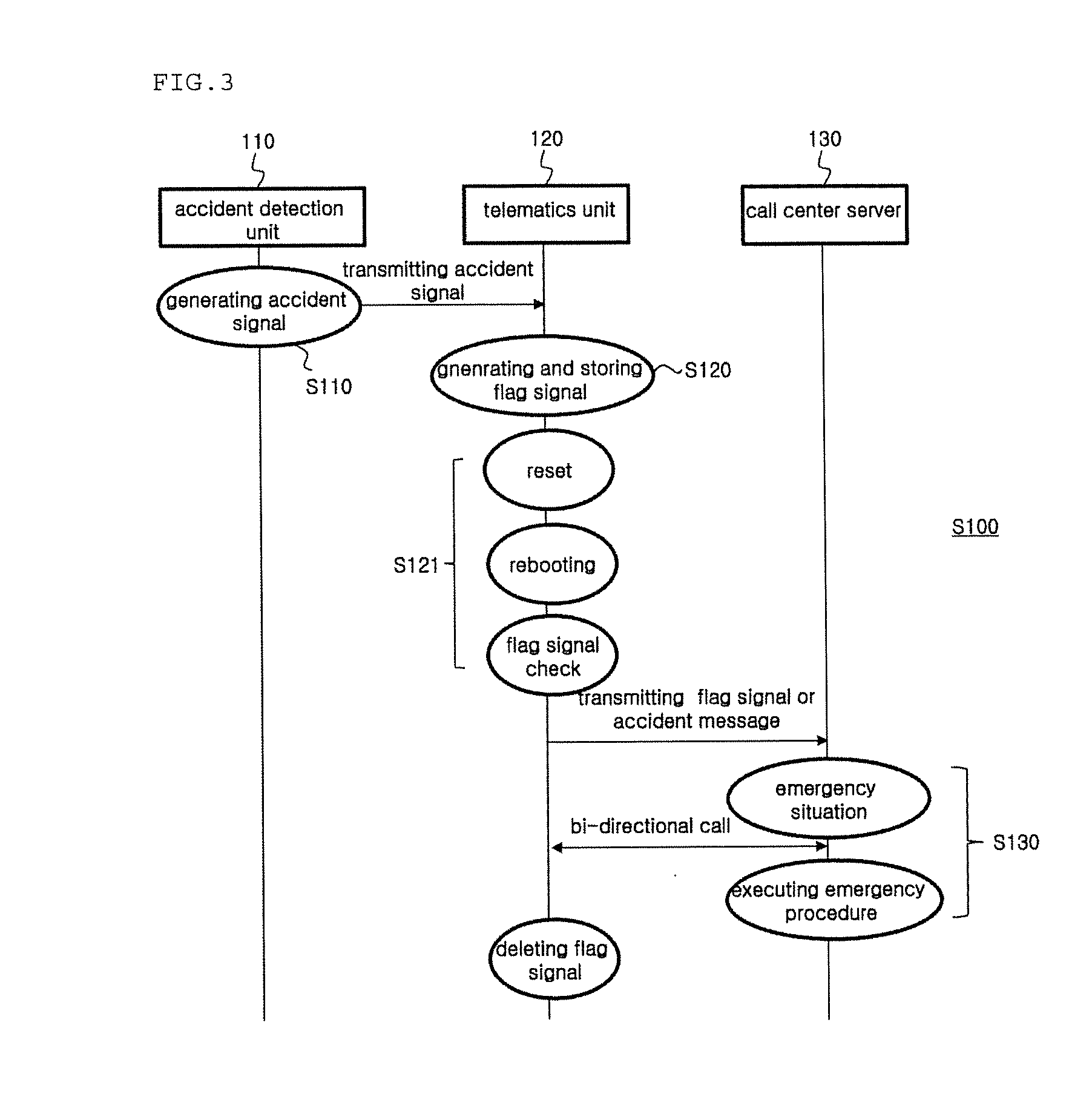
[0018]A telematics terminal can include an accident signal receiver configured to receive an accident signal generated from an accident detection unit sensing collision strength. Engaged with the accident signal receiver, a flag signal generator can generate a flag signal in response to the accident signal and to store the flag signal. Even when a reset is occurred in response to the accident signal, a flag signal confirmation unit can check or confirm the flag signal stored before the reset. Engaging with flag signal confirmation unit, the signal transmitter can automatically transmit at least one of the flag signal and an accident message generated based on the flag signal into the call center server.
[0019]The accident signal receiver can receive the accident signal regarding the collision strength from an airbag.

Problems solved by technology

Generally, an automobile accident causes damage or human life.
Procedures and costs to determine the cause of the accident, and to deal with the aftermath, may become complicated.
For example, the procedures and the costs may be difficult to determine because no eye witness exists or all drivers and passengers have passed away after the accident.
However, since it occasionally occurs that the telematics device is reset by detecting the automobile accident, the emergency handing apparatus cannot properly operate.
Accordingly, it is a problem that the procedures to determine the cause of the accident, and to deal with the aftermath, may not address.

Method used


Image

  • Car emergency system and method of emergency measures using the car emergency system
  • Car emergency system and method of emergency measures using the car emergency system
  • Car emergency system and method of emergency measures using the car emergency system

Examples


Embodiment Construction

[0034]Reference will now be made in detail to the preferred embodiments of the disclosure, examples of which are illustrated in the accompanying drawings. In the drawings, the same elements are denoted by the same reference numerals, and a repeated explanation thereof will not be given. The suffixes “module” and “unit” of elements herein are used for convenience of description and thus can be used interchangeably and do not have any distinguishable meanings or functions.

[0035]The terms “a” or “an”, as used herein, are defined as one or more than one. The term “another”, as used herein, is defined as at least a second or more. The terms “including” and / or “having” as used herein, are defined as comprising (i.e. open transition). The term “coupled” or “operatively coupled” as used herein, is defined as connected, although not necessarily directly, and not necessarily mechanically.

[0036]Also, in the description of embodiments, terms such as first, second, A, B, (a), (b) or the like may...


PUM


Abstract

A vehicle emergency system includes an accident detection unit for detecting a collision strength to generate an accident signal, a telematics unit for generating a flag signal in response to the accident signal and for storing the flag signal, and a call center server for recognizing an emergency situation when the flag signal is delivered, and for executing an emergency procedure after emergency call, wherein the telematics unit, even when reset by the accident signal, checks the flag signal stored before reset, and automatically transmits at least one of the flag signal and an accident message generated based on the flag signal into the call center server.

Description

CROSS-REFERENCE TO RELATED APPLICATION[0001]This application claims the benefit of priority to Korean Patent Application No. 10-2014-0164257, filed on Nov. 24, 2014 with the Korean Intellectual Property Office, the disclosure of which is hereby incorporated by reference as if fully set forth herein.TECHNICAL FIELD[0002]The disclosure relates to a method and a system for car emergency, and more particularly to a system, emergency system and method, adapted in a vehicle, operable to detect an emergency situation when the vehicle is involved in an accident and to handle an emergency measure service.BACKGROUND[0003]Generally, an automobile accident causes damage or human life. Procedures and costs to determine the cause of the accident, and to deal with the aftermath, may become complicated.[0004]For example, the procedures and the costs may be difficult to determine because no eye witness exists or all drivers and passengers have passed away after the accident.[0005]To solve the above-...

Claims


Application Information

Patent Timeline
Patent Type & Authority Applications(United States)
IPC IPC(8): H04M3/51B60R21/0136G08B25/10H04W4/90
CPCH04M3/5116B60R2021/0027B60R21/0136G08B25/10G08B25/016G08B25/08
Inventor KIM, MIN CHEOL
Owner HYUNDAI MOTOR CO LTD
Why Eureka
Try Eureka