
Apparatus and method for engine backpressure reduction

a backpressure reduction and engine technology, applied in combination devices, exhaust treatment, liquid separation agents, etc., can solve the problems of significant reduction of engine power and increase fuel consumption

Inactive Publication Date: 2016-06-09
VIDA HLDG CORP
View PDF1 Cites 0 Cited by
  • Summary
  • Abstract
  • Description
  • Claims
  • Application Information

AI Technical Summary

Benefits of technology

The solution significantly reduces engine backpressure and improves fuel economy by evenly distributing gas flow and minimizing backpressure, resulting in a 33-50% decrease in backpressure and a 4.5-12% improvement in fuel economy.

Problems solved by technology

The interposition of a catalytic converter into the exhaust system can impede gas flow, creating backpressure that can significantly reduce engine power and increase fuel consumption.

Method used


Image

  • Apparatus and method for engine backpressure reduction
  • Apparatus and method for engine backpressure reduction
  • Apparatus and method for engine backpressure reduction

Examples


Embodiment Construction

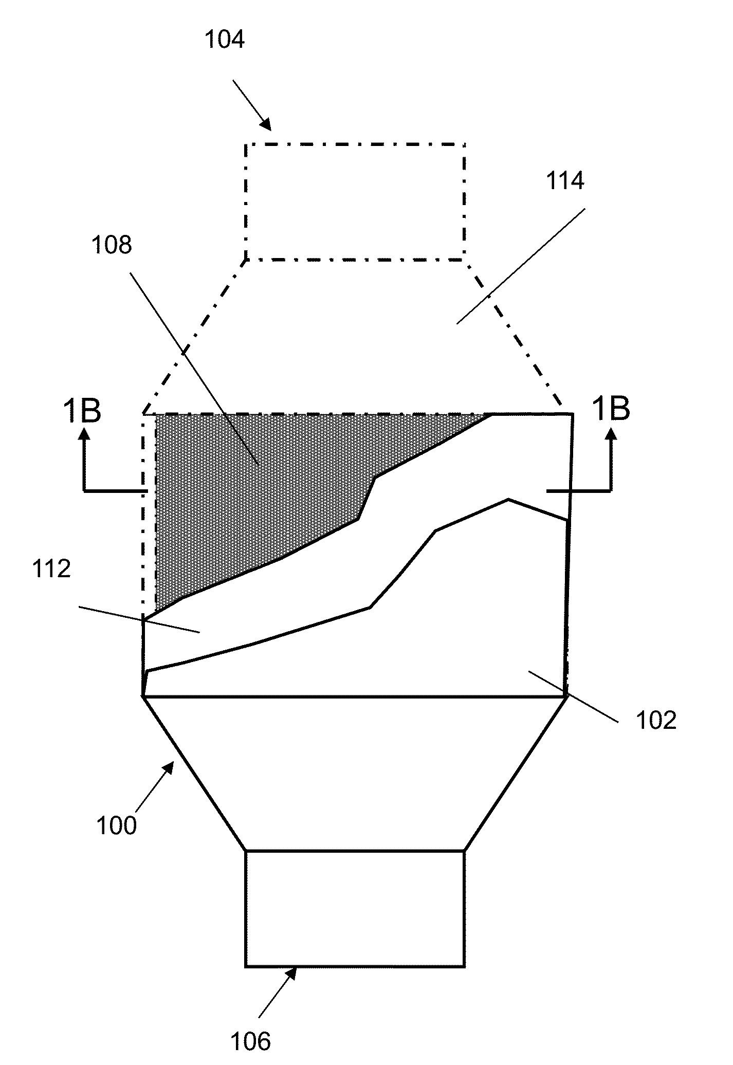
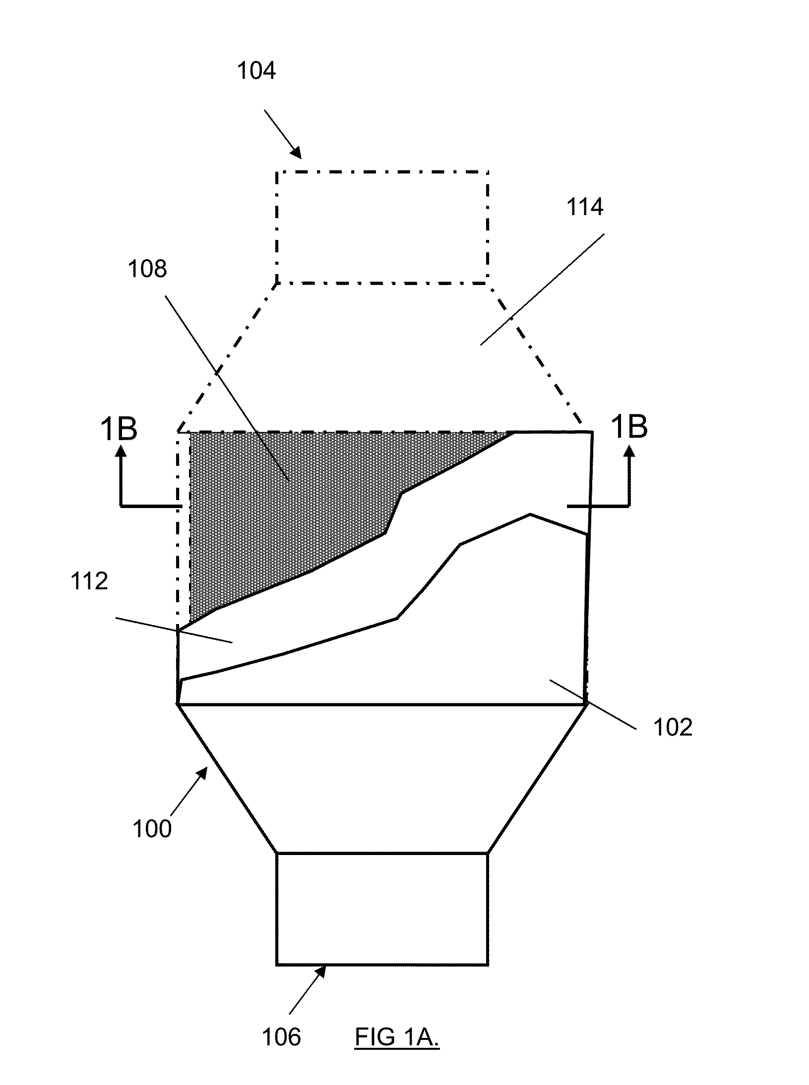
[0056]Exemplary embodiments of the invention are shown in FIGS. 1A through 2A.

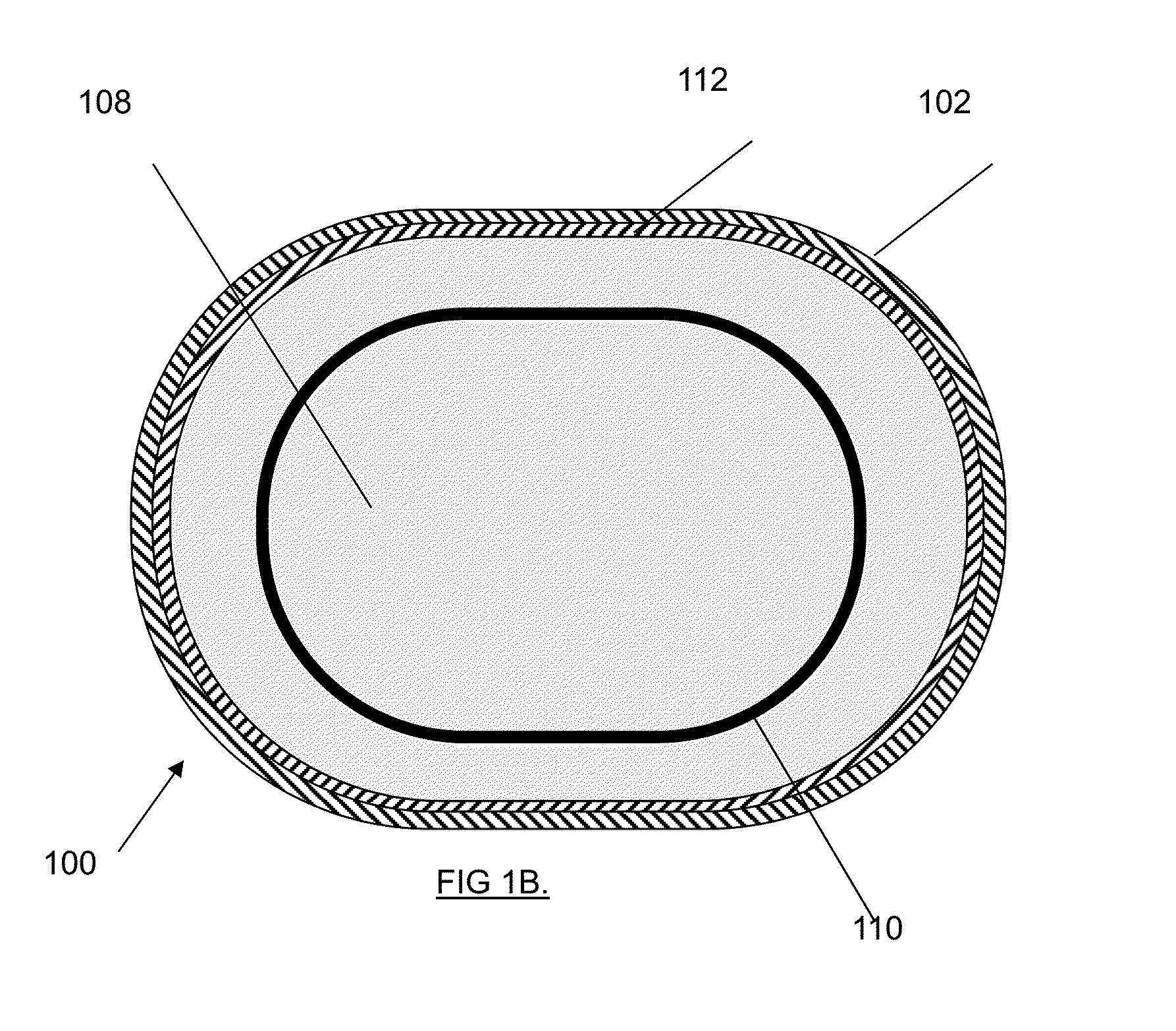
[0057]FIGS. 1A, 1B and 2A show a catalytic converter apparatus 100 according to the first exemplary embodiment of the invention.

[0058]This apparatus 100 is for use in an exhaust system of an internal combustion engine (not shown) and will be seen to include a housing 102, a gas inlet 104, a gas outlet 106 spaced apart from the inlet 104 and an oval substrate element 108 that substantially fills the housing 102 in a radial or lateral dimension relative to an axis of gas flow from the inlet 104 to the outlet 106. The substrate element 108 contains an oval flow redistribution element 110 made out of an insulative material that thermally and physically separates the substrate into a central zone and a tubular outer zone surrounding the central zone. Each of the central zone and the outer zone is an extruded ceramic honeycomb coated with catalytic material and, but for the shapes and orientation to one another,...


PUM


Abstract

An improved catalytic substrate for use with a can in an automotive exhaust system. The improvement includes an insulation material thermally separating the substrate into a central zone and an outer zone surrounding the central zone. The insulation material, central zone and outer zone collectively defining a modified substrate. The insulation material is adapted such that in an operating condition, the gas flow through the modified substrate is characterized by a static pressure that, on the upstream-facing surface of the modified substrate has a peak at a point generally central to the upstream-facing surface of the modified substrate; as the upstream-facing surface extends radially away from the point to the periphery, decreases, but for a surge after the upstream-facing surface extends beyond the insulation material.

Description

CROSS-REFERENCE TO RELATED APPLICATIONS[0001]This application is a continuation application of U.S. patent application Ser. No. 14 / 359,540 filed May 20, 2014 entitled “Apparatus and Method for Engine Backpressure Reduction” which is a national phase application of PCT / CA2013 / 000663 Jul. 19, 2013 claims priority to U.S. Provisional Patent Application Ser. No. 61 / 675,483, filed Jul. 25, 2012, U.S. Provisional Patent Application Ser. No. 61 / 673,394, filed Jul. 19, 2012, U.S. Provisional Patent Application Ser. No. 61 / 830,409, filed Jun. 3, 2013 and U.S. Provisional Patent Application Ser. No. 61 / 839,083, filed Jun. 25, 2013, which are each herein incorporated by reference.BACKGROUND OF THE INVENTION[0002]1. Field of The Invention[0003]The invention relates to the field of catalytic converters.[0004]2. Description of the Related Art[0005]Catalytic converters are widely used in motor vehicle exhaust systems to reduce the toxicity of emissions. In a typical catalytic converter, a substrat...

Claims


Application Information

Patent Timeline
Patent Type & Authority Applications(United States)
IPC IPC(8): B01D53/94F01N3/28
CPCB01D53/94F01N2260/06F01N3/2828F01N3/2892F01N2260/14F01N2330/60Y02A50/20F01N3/08
Inventor PLATI, STEFANOBLAGOJEVIC, VOISLAVKOYANAGI, GREGORY KIYOSHI
Owner VIDA HLDG CORP
Features
  • Generate Ideas
  • Intellectual Property
  • Life Sciences
  • Materials
  • Tech Scout
  • Unparalleled Data Quality
  • Higher Quality Content
  • 60% Fewer Hallucinations
Learn More