
Fluid connector with a swivel body

Active Publication Date: 2016-06-09
OTIKER NJ INK
View PDF15 Cites 0 Cited by
  • Summary
  • Abstract
  • Description
  • Claims
  • Application Information

AI Technical Summary

Benefits of technology

The invention provides a fluid connector that can rotate at various angles to prevent excessive stress and strain on the joint between the connector and the hose. This can help to prolong the life of the connector and hose by preventing damage to the seals.

Problems solved by technology

This fixed, rigid configuration causes complications for the positioning of fluid hoses since the hoses must be bent and contorted in order to fit properly.
If a fluid hose is bent or contoured in excess, this can place excessive stress and strain on the connection between the fluid connector and the fluid hose, causing the connection to become weak.
Additionally, the connection between the fluid connector and fluid hose may leak fluid due to an improper fit which in turn could cause excessive fluid loss of critical components such as the engine, causing overheating and possible damage if not discovered and fixed.
Unfortunately, if the angle at which the fluid connector is bent is also fixed, this doesn't solve the problem if the connected components are rearranged in a new configuration.
Unfortunately, Brown fails to disclose a type of securement means other than the concave seal itself.
If excessive force is placed on the swivel fitting, the seal will fail and fluid passing through the fitting may potentially leak.
Additionally, Brown fails to disclose a method of securing the fitting to a fluid transfer component.

Method used


Image

  • Fluid connector with a swivel body
  • Fluid connector with a swivel body
  • Fluid connector with a swivel body

Examples


Embodiment Construction

[0023]At the outset, it should be appreciated that like drawing numbers on different drawing views identify identical, or functionally similar, structural elements of the invention. It is to be understood that the invention as claimed is not limited to the disclosed aspects.

[0024]Furthermore, it is understood that this invention is not limited to the particular methodology, materials and modifications described and as such may, of course, vary. It is also understood that the terminology used herein is for the purpose of describing particular aspects only, and is not intended to limit the scope of the present invention.

[0025]Unless defined otherwise, all technical and scientific terms used herein have the same meaning as commonly understood to one of ordinary skill in the art to which this invention pertains. It should be understood that any methods, devices or materials similar or equivalent to those described herein can be used in the practice or testing of the invention. The assem...


PUM


Abstract

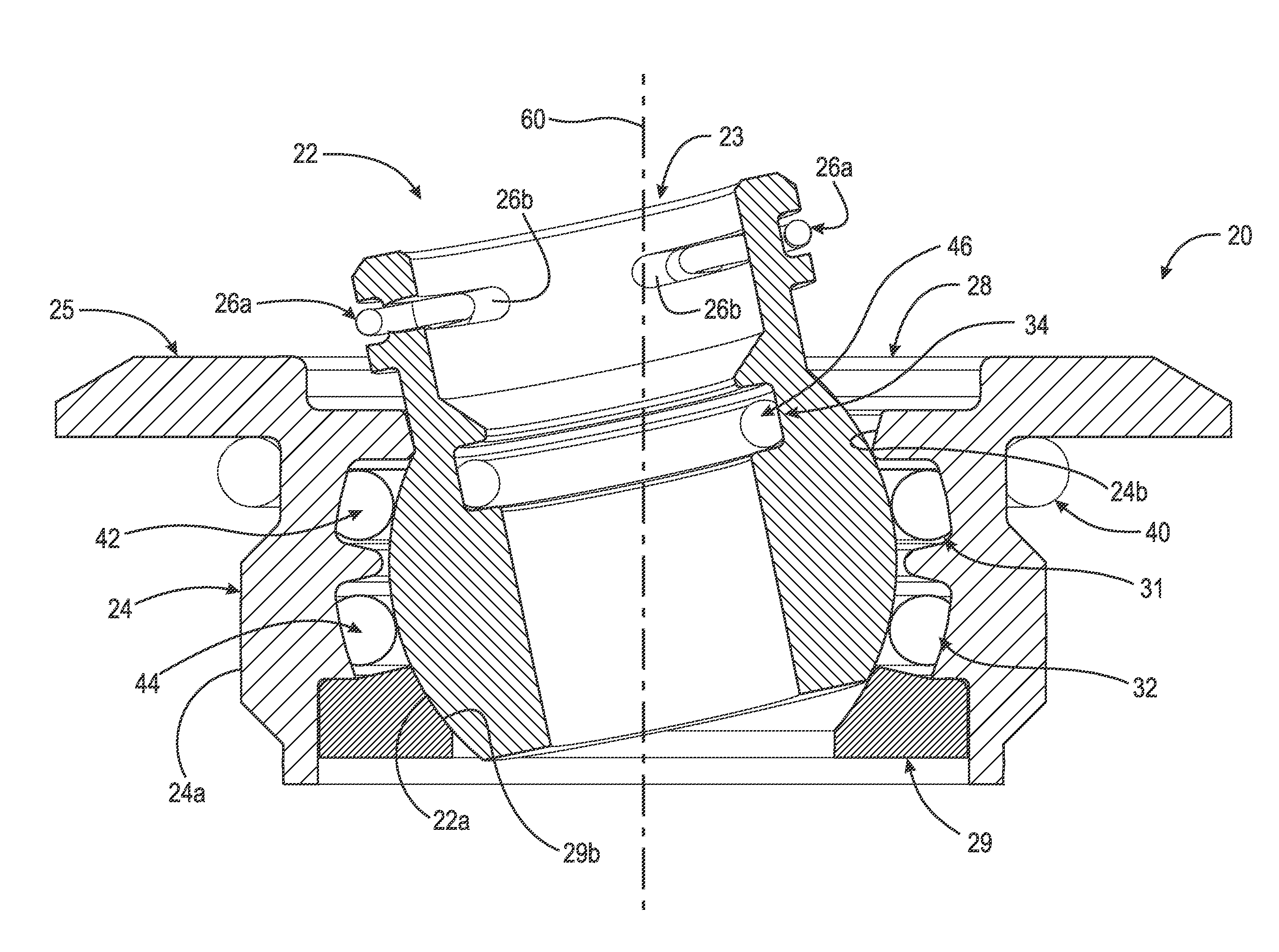
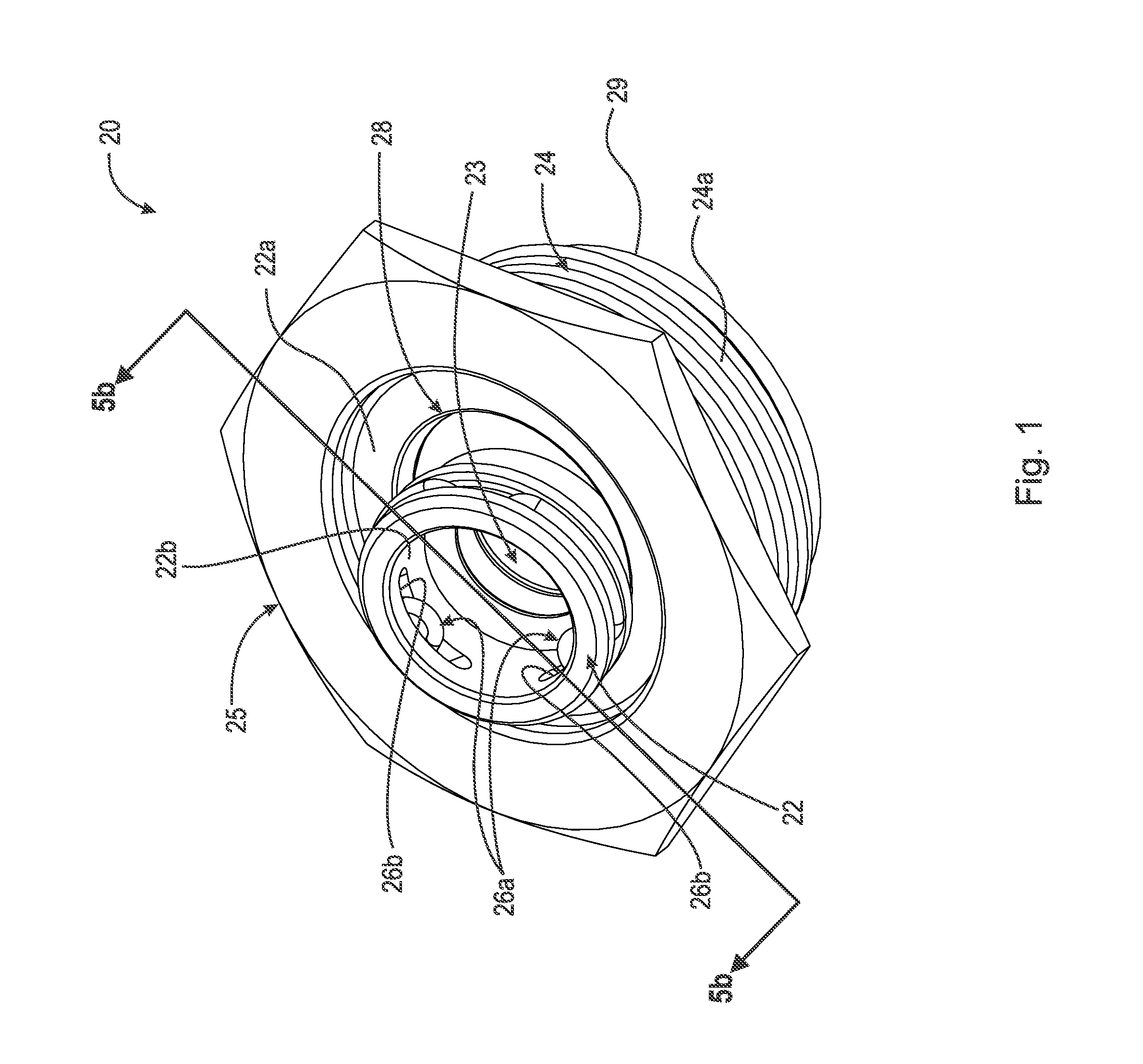
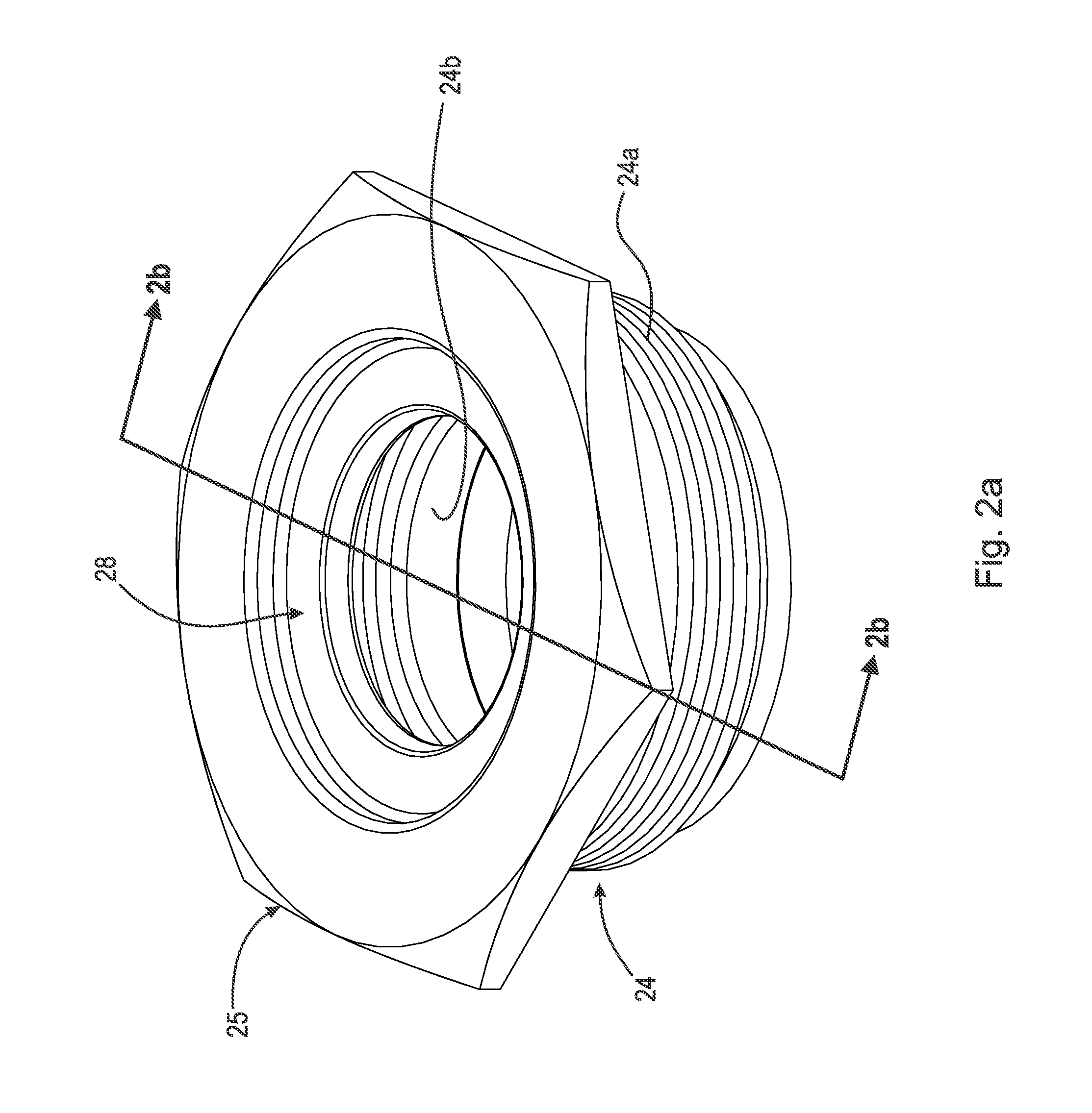
A fluid connector comprising a base having a first through-hole concentrically positioned therein, the base comprising a first inner surface and a first outer surface, the base comprising at least one annular groove extending radially outwardly from the first inner surface, at least one ring-shaped seal, each seal located within the at least one annular groove, a washer positioned within the first through-hole, the washer having an inwardly facing partially spherical surface, and, a body having a second through-hole positioned therein, the body comprising a second inner surface and a second outer surface, wherein the second outer surface is partially spherical in shape, wherein the second outer surface of the body engages the at least one seal and the inwardly facing partially spherical surface of the washer, wherein the body is arranged to swivel within the second through-hole, and to pass fluid through the second through-hole.

Description

FIELD OF THE INVENTION[0001]The invention relates generally to a fluid connector, and, more specifically, to a fluid connector with a body which allows for swiveling of the body to prevent excessive stress and strain on the fluid connector.BACKGROUND OF THE INVENTION[0002]Fluid connectors are integral components for automotive applications. Since an automotive system is made up of various components such as a radiator, transmission, and engine, fluid must be able to travel not only within each component but also between components. An example of fluid traveling between components is the transmission fluid traveling from the transmission to the transmission oil cooler in order to lower the temperature of the transmission fluid. Fluid predominantly moves between components via flexible or rigid hoses which connect to each component by fluid connectors.[0003]Fluid connectors are typically configured in a fixed orientation with respect to inlet and outlet, regardless of what vehicle the...

Claims


Application Information

Patent Timeline
IPC IPC(8): F16L27/06F16L15/08F16L37/084F16L21/03F16L21/08
CPCF16L27/06F16L21/03F16L15/08F16L37/0841F16L21/08F16L37/144F16L27/073F16L37/52
Inventor KUJAWSKI, JR., JAMES A.
Owner OTIKER NJ INK
Learn More