Tensioning device for a chain drive

Active Publication Date: 2017-12-14
SCHAEFFLER TECH AG & CO KG
View PDF2 Cites 4 Cited by
  • Summary
  • Abstract
  • Description
  • Claims
  • Application Information

AI Technical Summary

Benefits of technology

The present invention provides a tensioning device with a durable pressure relief valve unit. The valve seat is enclosed by a receptacle that forms a press fit with the inner surface of the clamping piston, preventing direct contact between the hardened surfaces. This design reduces manufacturing costs and allows for flexible tolerances. The tensioning device also includes a spring that can be tailored to different requirements. The invention is particularly useful in chain drives for internal combustion engines, reducing stress on the control chain and improving durability over the service life.

Problems solved by technology

Excessive stress on the pressure relief valve may result in material damage, thus impairing the durability of its properties.
However, this results in a conflict with the additional requirement of allowing cost-effective manufacture and installation of the preassemblable pressure relief valve unit.

Method used


Image

  • Tensioning device for a chain drive
  • Tensioning device for a chain drive
  • Tensioning device for a chain drive

Examples


Embodiment Construction

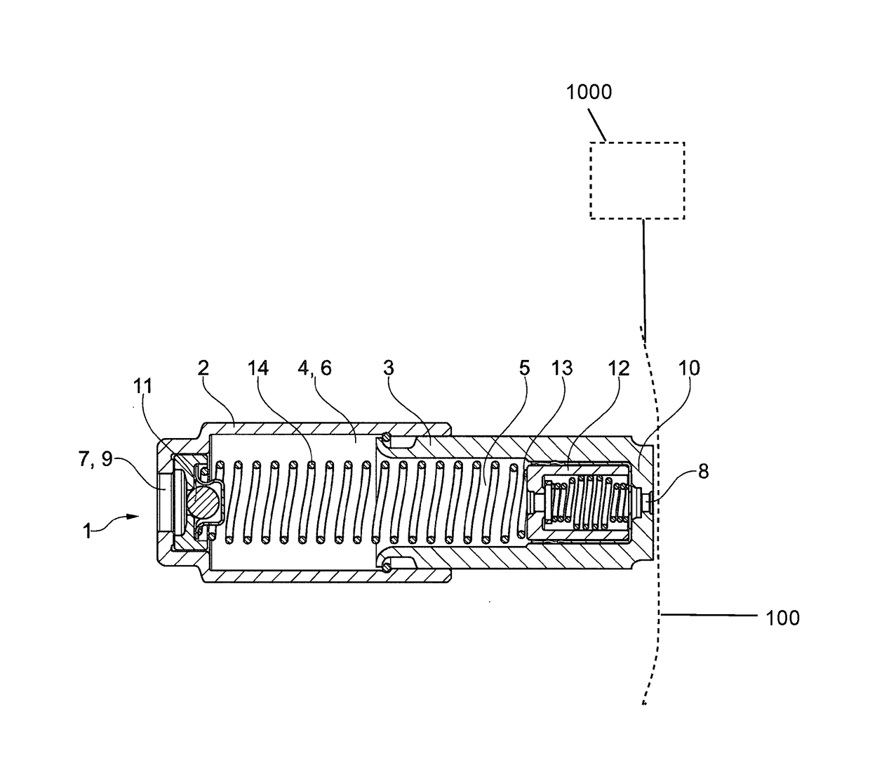
[0018]FIG. 1 shows a hydraulic tensioning device 1 for a chain drive of an internal combustion engine 1000 shown schematically in a longitudinal section. A chain drive includes a drive chain wheel that is connected to the crankshaft, an output chain wheel that is connected to a camshaft, and a control chain 100 shown schematically that connects the drive chain wheel to the output chain wheel. The drive torque of the crankshaft is transmitted to the camshaft via the tight span of the drive control chain. The control chain is tensioned at its slack span to be able to ensure its functionality over the operating period. For this purpose, the control chain is acted on by a tension force with the aid of the tensioning device.

[0019]Hydraulic tensioning device 1 is made up of a housing 2, and a clamping piston 3 that is axially displaceably guided in a housing bore 4 of housing 2. Clamping piston 3 is designed with a piston cavity 5, which together with the housing bore of the housing forms...


PUM


Abstract

A hydraulic tensioning device for a chain device, having a housing and having a clamping piston guided displaceably in a housing bore of the housing, the clamping piston having a piston cavity with a hardened inner circumferential surface, and also having a pressure relief valve unit arranged in the piston cavity. The pressure relief valve unit (12) is a preassemblable unit and includes a spring (18), a closing body (17) and a valve seat (16) and also a receptacle (15, 26) at least partially enclosing the valve seat (16), wherein the valve seat (16) is made of a metal material, has an at least partially hardened surface and wherein the receptacle (15, 26) forms a press-fit with the inner circumferential surface of the clamping piston (3).

Description

[0001]The present invention relates to a hydraulic tensioning device for a chain drive of an internal combustion engine. Chain drives generally include a drive chain wheel that is connected to the crankshaft, an output chain wheel that is connected to a camshaft, and a control chain that connects the drive chain wheel to the output chain wheel. The drive torque of the crankshaft is transmitted to the camshaft via the tight span of the drive control chain. The control chain is tensioned at its slack span in order to be able to ensure its functionality over the operating period. For this purpose, the control chain is acted on by a force with the aid of a tensioning device.BACKGROUND[0002]DE 10 2011 079 184 A1 provides a hydraulic tensioning device for an internal combustion engine. The device includes a housing and a hollow piston which is movable in the housing, and which together with the housing delimits a pressure chamber. Situated within the hollow piston is a pressure relief val...

Claims


Application Information

Patent Timeline
IPC IPC(8): F16H7/08
CPCF16H7/08F16H2007/0891F16H2007/0863F16H2007/0814F16K17/0413F16H2007/0859F16H2007/0806
Inventor FISCHER, MARKUS
Owner SCHAEFFLER TECH AG & CO KG
Why Eureka
Try Eureka