Apparatus for receiving a functional unit for a power tool and method for fastening a receiving apparatus of this kind to a power tool

a technology of functional units and power tools, applied in the field of apparatus for receiving functional units of power tools, can solve the problems of inaccurate work results which have to be reworked or repeated, the power tool is not being guided in an optimal straight line, and the work is not being done in a timely manner, so as to achieve weight-optimized working, the effect of rapid manner

Pending Publication Date: 2022-06-02
HILTI AG
View PDF35 Cites 0 Cited by
  • Summary
  • Abstract
  • Description
  • Claims
  • Application Information

AI Technical Summary

Benefits of technology

[0011]The present invention provides, in particular, a particularly stable fastening solution with which a functional unit can be securely fastened to a power tool. If the fastening mechanism is combined with an additional dovetail connection, a “double” fastening solution can advantageously be provided for the functional unit. Within the meaning of the invention, the term “double” preferably means that, in the context of the fastening solution, a dovetail connection is combined with the fastening mechanism in order to ensure particularly stable and vibration-resistant fastening. In a particularly preferred embodiment of the invention, an additional component, such as the functional unit or an accessory, can be attached to a power tool. The power tool may be, for example, a slot device with which, for example, slots can be cut into walls in order to lay cables therein. The double fastening advantageously ensures that the functional unit is fitted to the power tool at the correct angle and in the correct position. Furthermore, the proposed fastening solution ensures that the vibrations which act on the functional unit are minimized. This constitutes a substantial advantage of the present invention since, in this way, the mechanical loads on the optical system and the internal electronics system of the functional unit can be considerably reduced.
[0012]A further advantage of the invention is that the functional unit can be fastened to the power tool in a particularly rapid manner and practically without tools. This makes it possible to fit the functional unit to the power tool only in the work phases in which, for example, the projection of a laser beam is required for using the power tool. This allows the power tool to be used without the functional unit at all other times. As a result, the weight of the power tool in these work phases in which the tool is used without the functional unit can be significantly reduced in comparison to those power tools in which the functional unit is permanently fitted or is integrated into the power tool. In particular, the invention allows weight-optimized working with the power tool. Owing to the two-sided fastening approach, the invention further allows dimensional fluctuations in the production of the receiving apparatus due to resulting tension conditions to be compensated for. Owing to the fastening, in particular, manufacturing-related measurement inaccuracies can be compensated for and therefore the laser light can be positioned in an extremely exact manner.
[0013]In a preferred exemplary embodiment, the invention comprises a preferably T-shaped carrier or pin which can be arranged in a front region of the power tool or on an end side of the power tool. In alternative configurations of the inventions, V-shaped or U-shaped pins can also be used. The use of a carrier or pin on the power tool, which carrier or pin interacts with a cutout on the functional unit, preferably leads to the formation of a dovetail connection mechanism which, in the context of the invention, can interact with the fastening mechanism in order to enable stable fastening of the functional unit with minimized transmission of vibrations to the functional unit. It is preferred within the meaning of the invention that the pin on the power tool is clasped by the cutout of the functional unit.
[0014]In an exemplary embodiment of the invention, it is preferred for the insert part to be inserted into the opening of the receiving apparatus when the two halves of the apparatus are not connected to one another. When a customer purchases the receiving apparatus, the two halves of the receiving apparatus are preferably connected to one another and the insert part is located within the receiving apparatus. In other words, it is preferred within the meaning of the invention for the insert part to be located in a preferably hollow interior of the receiving apparatus, in particular in the opening of the receiving apparatus. The insert part preferably has a cylindrical basic body, so that it can be rotated in the hollow-cylindrical opening of the receiving apparatus that is preferably at least partially designed as a bore.
[0015]It is preferred within the meaning of the invention for the insert part to comprise a slot by way of which the insert part can be rotated in the opening, wherein the slot is arranged on the side of the insert part that is averted from the raised portion. It is preferred within the meaning of the invention for the slot of the insert part to be visible in the opening on the side of the receiving apparatus that is averted from the power tool. It is furthermore preferred within the meaning of the invention for the insert part to be movable from the fastened to an unfastened state, or vice versa, by a rotation process in the opening or the bore of the receiving apparatus. The insert part preferably has a raised portion which faces the power tool when the insert part is located in the receiving apparatus. It is preferred within the meaning of the invention for the power tool to comprise a hook for fastening the receiving apparatus to the power tool. This hook can be arranged, for example, on a side surface or on an top side of the power tool. The fastened state is preferably characterized in that the hook of the power tool is in engagement with the raised portion of the insert part. In the fastened state, the receiving apparatus is preferably connected to the power tool and can be moved together with it. The unfastened state is preferably characterized in that the hook of the power tool is not in engagement with the raised portion of the insert part. As a result, the proposed fastening mechanism advantageously has no fastening effect between the receiving apparatus and the power tool in the unfastened state, and the receiving apparatus can be removed, detached or disconnected from the power tool. The receiving apparatus can be detached, in particular, by also releasing the additional dovetail connection by way of, for example, lifting away or pulling away the receiving apparatus upward from the pin as a counterpart of the dovetail slot.
[0016]It is preferred within the meaning of the invention for the front region of the receiving apparatus to have a substantially trapezoidal basic shape when viewed from the side. Within the meaning of the invention, the short trapezoidal top side preferably points forward, while the longer trapezoidal bottom side faces the power tool. The power tool preferably has a substantially planar end side to which the receiving apparatus can be fastened. The power tool preferably has a pin on the front or end side, wherein this pin is designed to form a dovetail connection together with the cutout of the receiving apparatus.

Problems solved by technology

However, it has been found —for example due to warping, which can easily occur during production of the corresponding components—deviations and inaccuracies can occur as a result.
Particularly if the functional unit is a line laser device, imprecise representations of the desired projection target can result, and these can lead to the power tool not being guided in an optimal straight line.
Non-straight line guidance can lead to inaccurate work results which have to be reworked or repeated if necessary.
Furthermore, projection sharpness can be lost owing to vibrations at the fastening point between the functional unit and the power tool.
This can happen particularly if the functional unit becomes detached from the power tool and is no longer fastened in a stable manner.
A further disadvantage of the permanently fitted functional units is that a system of this kind comprising a functional unit and a power tool necessarily has, owing to the functional unit being permanently carried along, a higher overall weight than easily removable functional units which can be fitted to the power tool only when required.

Method used


Image

  • Apparatus for receiving a functional unit for a power tool and method for fastening a receiving apparatus of this kind to a power tool
  • Apparatus for receiving a functional unit for a power tool and method for fastening a receiving apparatus of this kind to a power tool
  • Apparatus for receiving a functional unit for a power tool and method for fastening a receiving apparatus of this kind to a power tool

Examples


Embodiment Construction

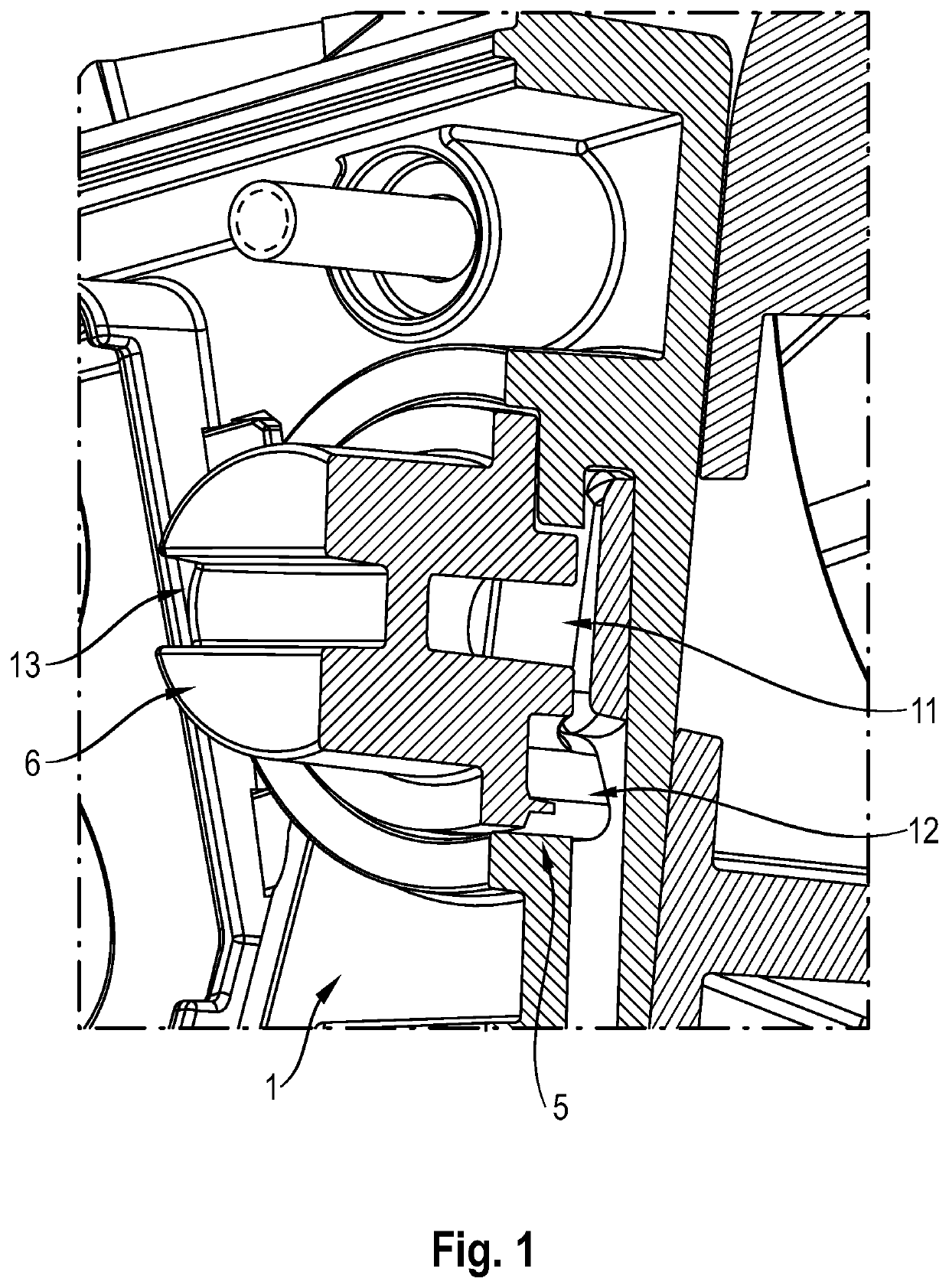
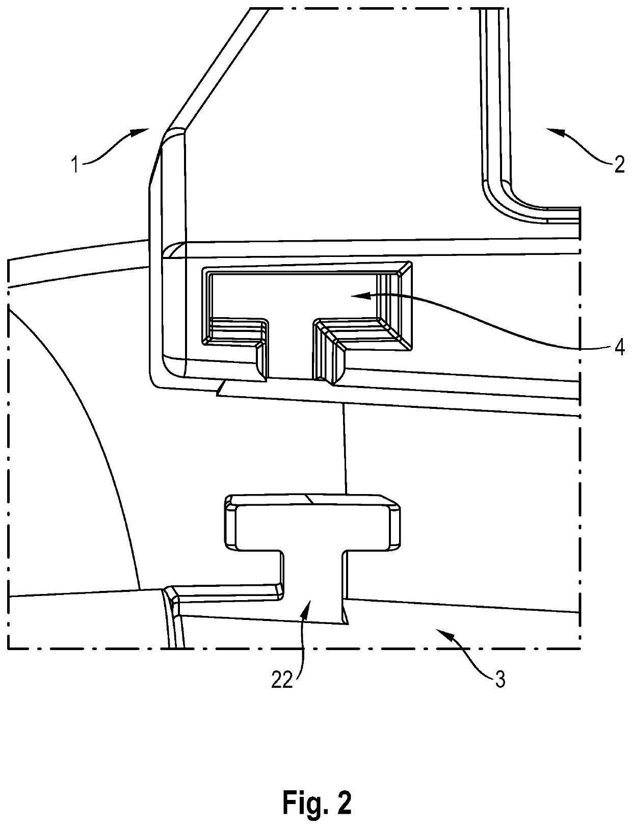
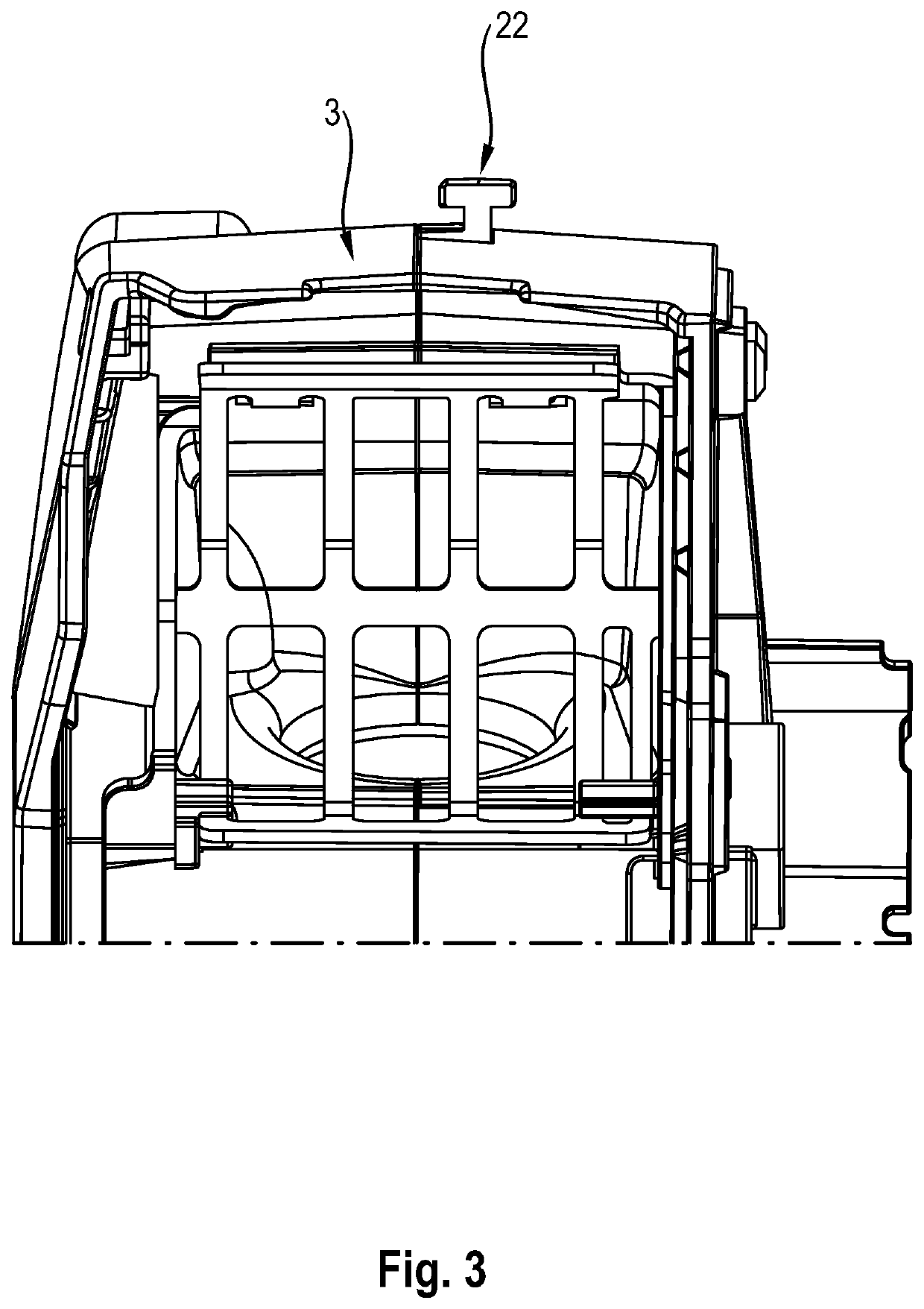
[0042]The figures will be used with a preferred embodiment to describe the method disclosed above for fastening a receiving apparatus (1) for a functional unit (2) to a power tool (3), wherein the method comprises the following steps:

a) providing a receiving apparatus (1) in an unfastened state, wherein the unfastened state of the receiving apparatus (1) is defined by a position of an insert part (6) in the receiving apparatus (1),

b) inserting a pin (22) of the power tool (3) into a cutout (4) of the receiving apparatus (1),

c) inserting a hook (11) of the power tool (3) into a slot (10) of the receiving apparatus (1),

d) rotating the insert part (6) within the receiving apparatus (1), so that the receiving apparatus (1) is moved from an unfastened to a fastened state and a connection between the power tool (3) and the receiving apparatus (1) is obtained.

[0043]FIG. 1 shows a view of a preferred refinement of the insert part (6) which, together with an opening (5) of the receiving appa...


PUM


Abstract

An apparatus for receiving a functional unit for a power tool, wherein the receiving apparatus can be fastened to the power tool by way of a fastening mechanism. A second aspect of the invention relates to a method for fastening a receiving apparatus of this kind to a power tool. In the fastening mechanism, a rotatable insert part can be inserted into an opening of the receiving apparatus and can be moved from an unfastened to a fastened state by this rotational movement. In the fastened state, a hook of the power tool engages with a raised portion of the insert part.

Description

BACKGROUND[0001]The present invention relates to an apparatus for receiving a functional unit for a power tool, wherein the receiving apparatus can be fastened to the power tool by way of a fastening mechanism. A second aspect of the invention relates to a method for fastening a receiving apparatus of this kind to a power tool.SUMMARY OF THE INVENTION[0002]Various methods are known in the prior art for fastening functional units, such as line laser devices for example, to power tools. For example, it is proposed in the prior art to adhesively bond, screw and / or attach line laser devices to the power tools. However, it has been found —for example due to warping, which can easily occur during production of the corresponding components—deviations and inaccuracies can occur as a result. Particularly if the functional unit is a line laser device, imprecise representations of the desired projection target can result, and these can lead to the power tool not being guided in an optimal stra...

Claims


Application Information

Patent Timeline
Patent Type & Authority Applications(United States)
IPC IPC(8): B25F5/02
CPCB25F5/02B25F5/021
Inventor HUBER, FRANZVAN TAACK-TRAKRANEN, JOHN
Owner HILTI AG
Why Eureka
Try Eureka