Fuel supply installation in the form of a common-rail system of an internal combustion engine having a plurality of cylinders

a technology of common rail system and internal combustion engine, which is applied in the direction of liquid fuel feeder, machine/engine, fuel injecting pump, etc., can solve the problems of considerable dynamic pressure fraction, considerable damage risk, and expected problems

Inactive Publication Date: 2004-08-17
MAN ENERGY SOLUTIONS SA
View PDF11 Cites 13 Cited by
  • Summary
  • Abstract
  • Description
  • Claims
  • Application Information

AI Technical Summary

Benefits of technology

This object is achieved, according to the invention, by means of each individual accumulator unit of the pressure-accumulator line being designed in such a way that they each have an accumulator volume for serving at most approximately two cylinders. The position of an accumulator unit along the internal combustion engine and its length can therefore be selected in such a way that the shortest possible pressure-accumulator line can be constructed. In a particularly preferred way, an accumulator unit is designed in such a way that it has in each case an accumulator volume for serving two cylinders. By accumulator covers being provided in each case on both end faces, all the functional units are integrated into these in terms of fuel delivery and transfer, retrofitting on existing engine types with common-rail injection systems has been markedly simplified. All the hydraulic connections, and holding devices for positioning the accumulator units along the internal combustion engine, and also sealing-off elements for the accumulator unit, as well as functional units, such as a quantity-limiting valve, are located in the accumulator cover, so that a modular construction becomes possible in a simple way and, furthermore, operating reliability is increased, since the accumulator units, and therefore the entire pressure-accumulator line, are free of external forces which originate from holding devices and hydraulic connections which are now received by the accumulator covers designed according to the invention.
Finally, what is also achieved by arranging at least one separate pump accumulator in the high-pressure region between the high-pressure pump and the assembled pressure-accumulator line, the pump accumulator being connected to at least one accumulator cover of an accumulator unit of the pressure-accumulator line for fuel conveyance and being capable of being acted upon by at least one high-pressure pump, is that the dynamic pressure fractions generated by the pumps can be reduced considerably before the conveyed fuel, that is to say, for example, the heavy oil, is fed into the pump lines which ultimately lead into the pressure-accumulator line. Thus, furthermore, the mechanical load on the accumulator units is markedly reduced and the operating reliability of the entire fuel supply installation is increased.
It is to be seen as a further advantageous embodiment of the fuel supply installation that the accumulator units of the pressure-accumulator line can receive line pipes which are laid in the axial direction and which have throttle bores, so that all the accumulator units can be acted upon in parallel by fuel.

Problems solved by technology

As is known, because of the problematic corrosion and viscosity properties of heavy oil (tendency to paraffin separation, particularly at low temperature, when the internal combustion engine is in the state of rest), the engine and the fuel supply installation have to satisfy special preconditions.
Nevertheless, when the engine is in operation, problems continue to be expected, particularly with regard to the strength of the individual accumulator units, since the feed lines connecting them to one another issue as radial bores and form weak points there and therefore put at risk the stability of the common rail.
This results, in turn, in considerable dynamic pressure fractions, such as pressure hammers and pressure pulsations, which give rise, in turn, to high mechanical loads on the feed lines which entail a considerable risk of damage, such as leakages or breaks.
Thus, furthermore, the mechanical load on the accumulator units is markedly reduced and the operating reliability of the entire fuel supply installation is increased.

Method used


Image

  • Fuel supply installation in the form of a common-rail system of an internal combustion engine having a plurality of cylinders
  • Fuel supply installation in the form of a common-rail system of an internal combustion engine having a plurality of cylinders
  • Fuel supply installation in the form of a common-rail system of an internal combustion engine having a plurality of cylinders

Examples


Embodiment Construction

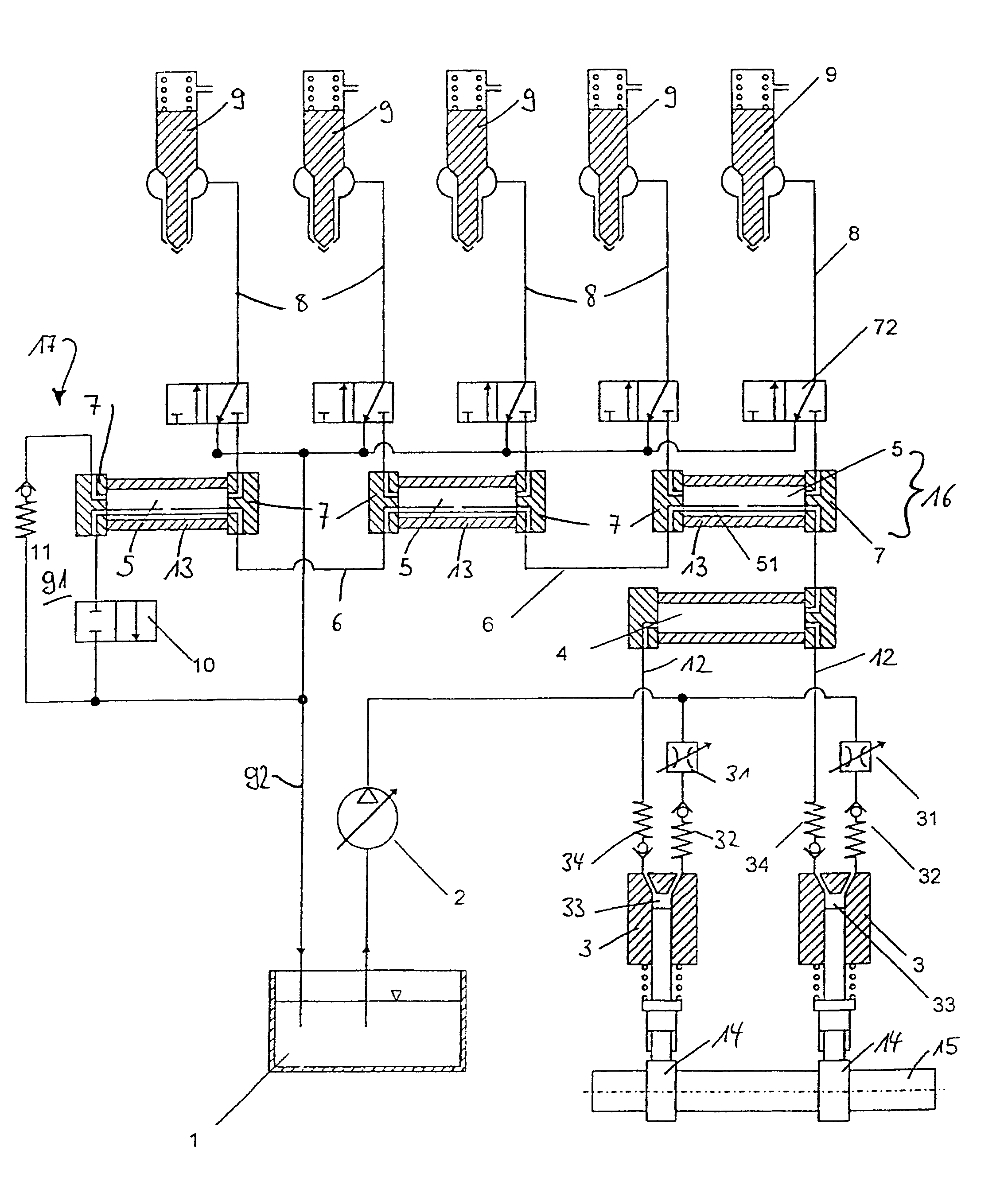
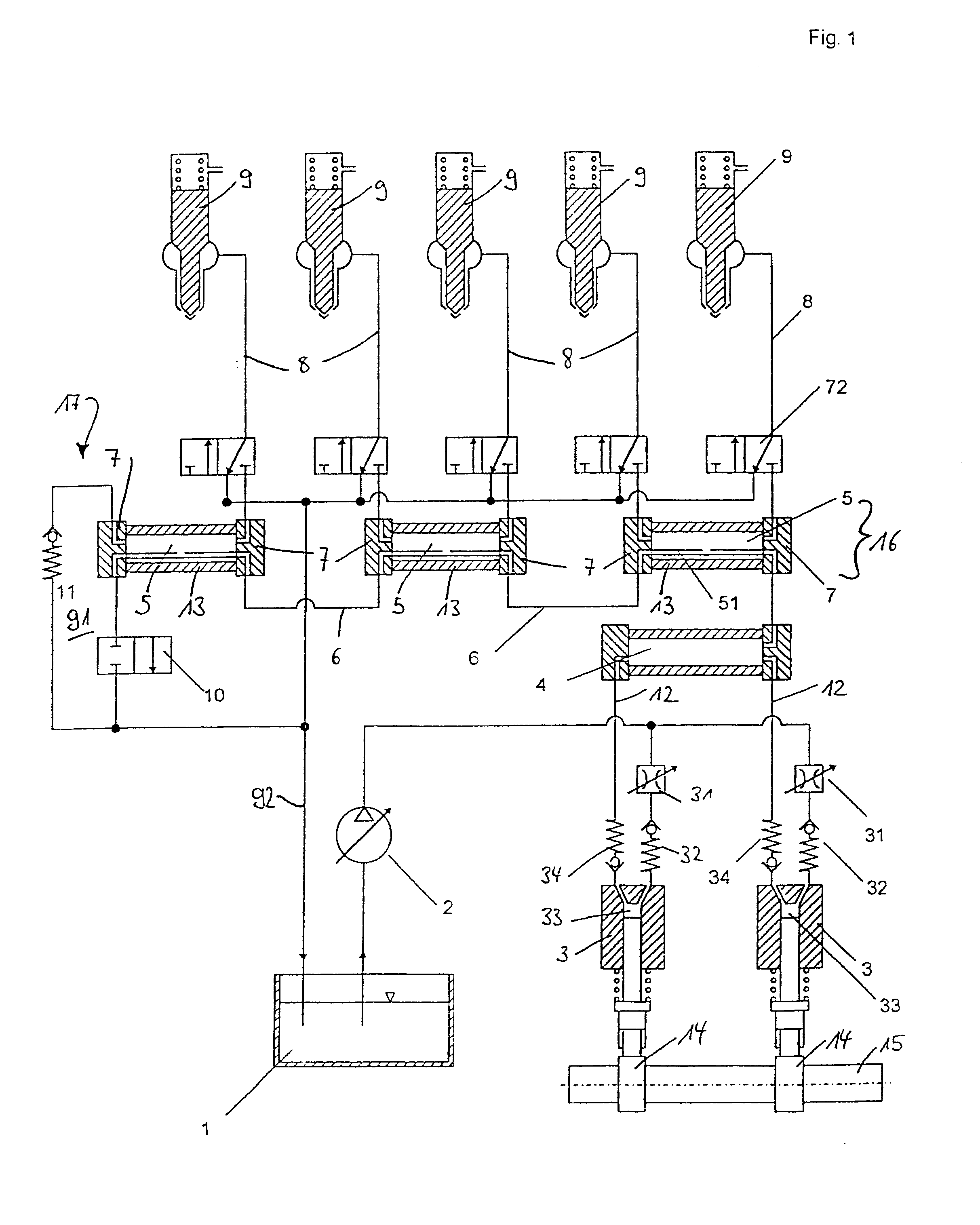
The diagram according to FIG. 1 shows a modularly constructed fuel supply installation in the form of a common-rail system for an internal combustion engine, not illustrated in any more detail, which operates according to the diesel process. This diesel engine is designed to operate with heavy oil which is conveyed out of a fuel tank 1 in the low-pressure region via a fuel low-pressure system 2 by means of a plurality of high-pressure pumps 3, in each case via separate pump lines 12, into a high-pressure region which follows the high-pressure pumps 3 downstream. The internal combustion engine, not illustrated, is a five-cylinder engine in which each cylinder is assigned an injector 9.

Provided in the high-pressure region between the high-pressure pumps 3 and the injectors 9 is a pressure-accumulator line 16 which is known by the term "common rail", is constructed from three separate accumulator units connected to one another by means of feed lines 6 and is distinguished by an interna...


PUM


Abstract

Fuel is conveyed by at least one high-pressure pump from a low-pressure region into a high-pressure region including a pressure-accumulator line consisting of at least two separate accumulator units connected to one another by means of feed lines, and to fuel injectors for the cylinders. The accumulator units each have an accumulator volume for serving at least two cylinders, and accumulator covers provided on both end faces. All the functional units are integrated into these accumulator covers in terms of fuel delivery and transfer, and at least one separate pump accumulator is arranged in the high-pressure region between the high-pressure pump and the assembled pressure-accumulator line. The pump accumulator is connected to at least one accumulator cover of an accumulator unit of the pressure-accumulator line for fuel conveyance and is capable of being acted upon by at least one high-pressure pump.

Description

1. Field of the InventionThe invention relates to a fuel supply installation in the form of a common-rail system of an internal combustion engine having a plurality of cylinders, in particular a large diesel internal combustion engine operated preferably with heavy oil, wherein the fuel is conveyed by a pumping device from a low-pressure region into a high-pressure region, the high-pressure region comprising a pressure-accumulator line consisting of at least two separate accumulator units connected to one another by means of feed lines, and fuel injectors for the cylinders are connected to the accumulator units. The invention also relates to individual components of a common-rail system which are suitable in a particularly advantageous way for use in a fuel supply installation according to the invention.2. Description of the Related ArtThis fuel supply installation is to be used, in particular, in large diesel internal combustion engines operated with heavy oil. As is known, because...

Claims


Application Information

Patent Timeline
Patent Type & Authority Patents(United States)
IPC IPC(8): F02M55/02F02M63/00F02M63/02F02M45/04F02M45/00F02B3/00F02B3/06F02M47/00
CPCF02D19/0657F02D19/0684F02M37/0064F02M45/04F02M55/025F02M63/0005F02M63/0007F02M63/0215F02M63/0225F02D19/0621F02B3/06F02M59/44F02F2007/0097F02M2200/315F02M2200/40Y02T10/36F02M2200/18Y02T10/30F02M55/02
Inventor MAIER, LUDWIGVOGEL, CHRISTIANSCHROTT, CHRISTOPHSONGEN, MATTHIASHLOUSEK, JAROSLAVKOGLER, BERNDGRASPEUNTER, CHRISTIANSASSNIK, HAGEN
Owner MAN ENERGY SOLUTIONS SA
Why Eureka
Try Eureka