Encapsulated multi-phase electronics heat sink

a multi-phase electronics and heat sink technology, applied in the field of encapsulated multi-phase electronics heat sinks and heat dissipation in electrical circuits, can solve the problems of multiple thermal choke points, the ability to effectively transfer excess heat to space has not kept pace with the demands of the higher-power electronics being employed, and none of the developed systems lend themselves to being easily integrated with an existing chip type or retrofitted to an existing circuit design. , to achieve the effect of facilitating fluid circulation and

Active Publication Date: 2007-12-13
THE BOEING CO
View PDF14 Cites 13 Cited by
  • Summary
  • Abstract
  • Description
  • Claims
  • Application Information

AI Technical Summary

Benefits of technology

[0009]An apparatus and method for cooling electronics is disclosed. An encapsulated inert non-conductive fluid is used to transfer heat directly from an electrical circuit to an external heat-sink. The electrical circuit may comprise a die on a substrate of a known type, e.g. a ceramic column grid array flip chip (CCGA), which is enclosed with a metallic cover. The metallic cover is sealed to an outer frame, which in turn is sealed to metallization on the top of the flip chip through a flexure, minimizing mechanical load imparted to the flip chip. This forms a hermetic cavity enclosing the die. This hermetic cavity is partially filled with an inert non conductive fluid, which vaporizes when heated. Condensation occurs on the inner surface of the metal cover where the heat may be conducted into the outer frame for removal (e.g. rejection from the spacecraft). For applications in zero gravity (or micro gravity), or under small adverse accelerations, a wicking structure may be employed in the hermetic cavity to facilitate fluid circulation within the cavity.
[0010]Embodiments of the invention enable high heat dissipation from an electrical die (e.g. up to approximately 50W), thus improving the electrical capabilities of a given circuit. A temperature rise of approximately 20° C. from a die to the heat-sink with a 50W dissipation may be achieved, equivalent to the current state of the art for a conventional 20W application specific integrated circuit (ASIC) in a spacecraft application.
[0013]Some examples of attached external heat transfer enhancement that can be achieved through modification of the metallic cover include attachment of conductive straps, use of a top cover with external extruded fins (for terrestrial convective environments), and use of a cover with an external cavity for attachment to conventional liquid cooling systems. In general, the surface area of the cover (e.g. external surface area) may be increased to much greater than that of the electronic die, reducing thermal resistances in the heat rejection path from the cover to the heat rejection medium attached to (or surrounding) the metallic cover. Further modification of the metallic cover can allow penetration into the cavity adjacent to the electronics, enabling direct impingement spray cooling onto the electronics to achieve further cooling enhancement.
[0014]Modifications of the metallic cover in conjunction with the flexure can allow separation of the thermal and mechanical paths such that loads transferred from the metallic cover to the fixed frame are not imparted directly to the sensitive electronic components while heat energy is still transferred from the electronics to the metallic cover.
[0015]In other embodiments, an outer frame fixed to a printed wiring board (PWB) surrounding the electronic circuit and supporting the metallic cover is used. Heat may be removed from the electronic circuit by being transferred in sequence from the non-conductive fluid to the metallic cover to the outer frame. The metallic cover may comprise a flexure sealed to metallization on top of the electronic circuit and sealed to the outer frame. The flexure can reduce mechanical load imparted to the electronic circuit.

Problems solved by technology

However, these designs commonly result in multiple thermal choke points.
Although circuit cooling has been developed using non-conductive liquid, such cooling systems require special architechtures and complex components which designed integrally with the circuit they are intended to cool.
However, none of the developed systems lend themselves to being easily integrated with an existing chip type or retrofitted to an existing circuit design.
In space applications, the ability to effectively transfer excess heat to space has not kept pace with the demands of the higher power electronics being employed.

Method used


Image

  • Encapsulated multi-phase electronics heat sink
  • Encapsulated multi-phase electronics heat sink
  • Encapsulated multi-phase electronics heat sink

Examples


Embodiment Construction

[0024]1. Overview

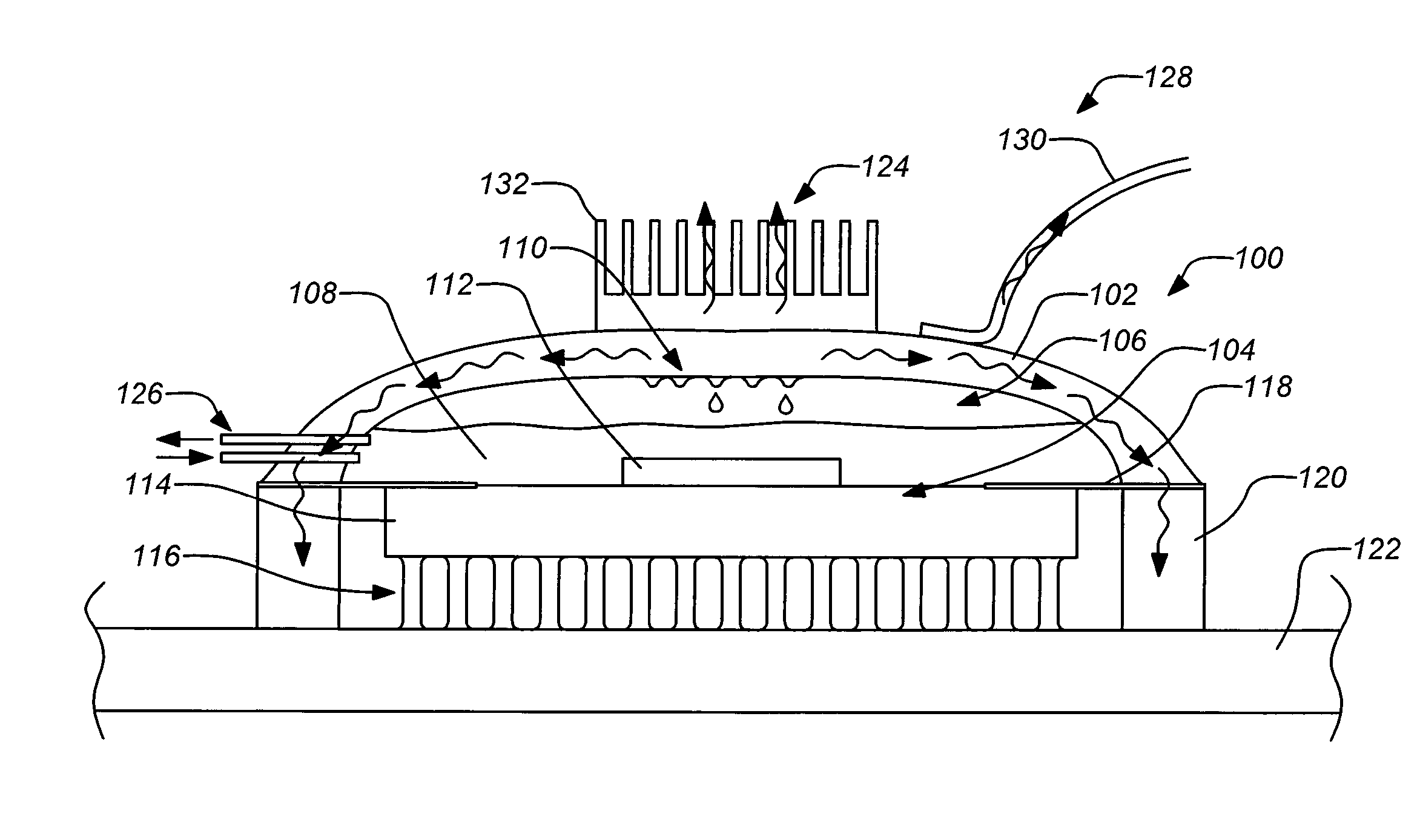
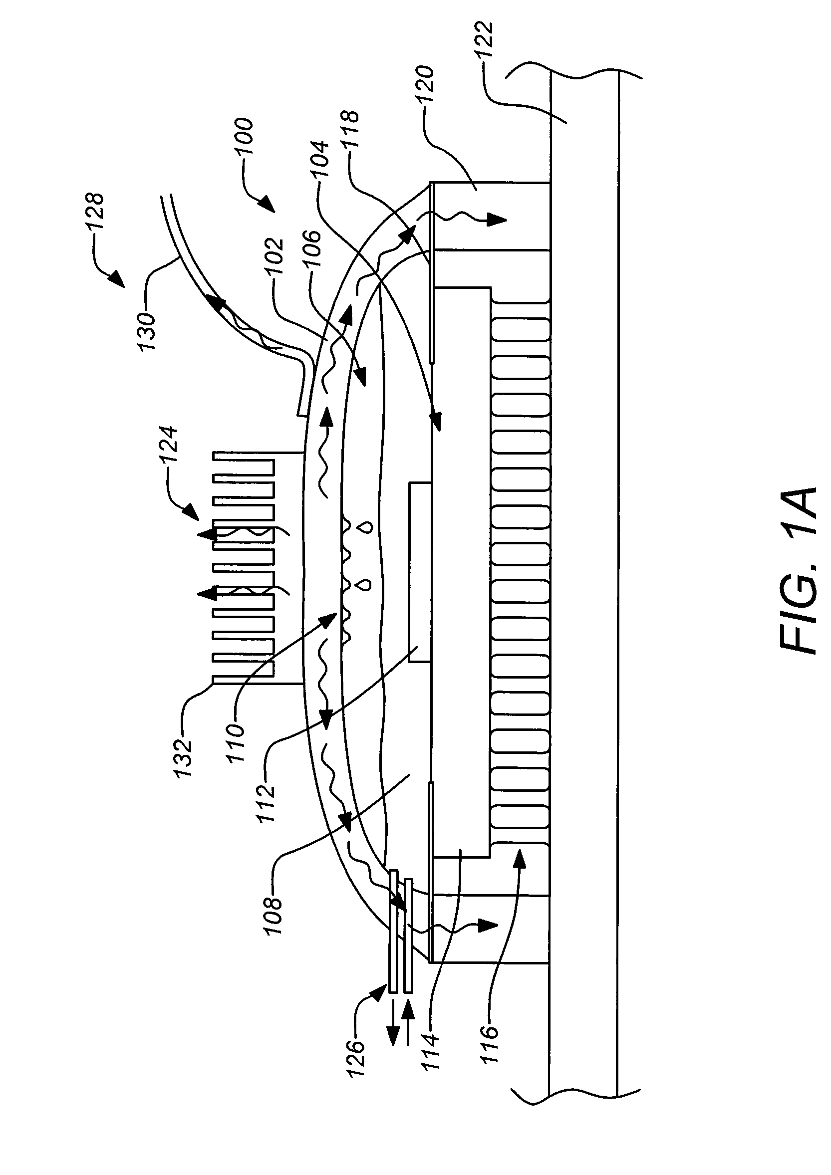
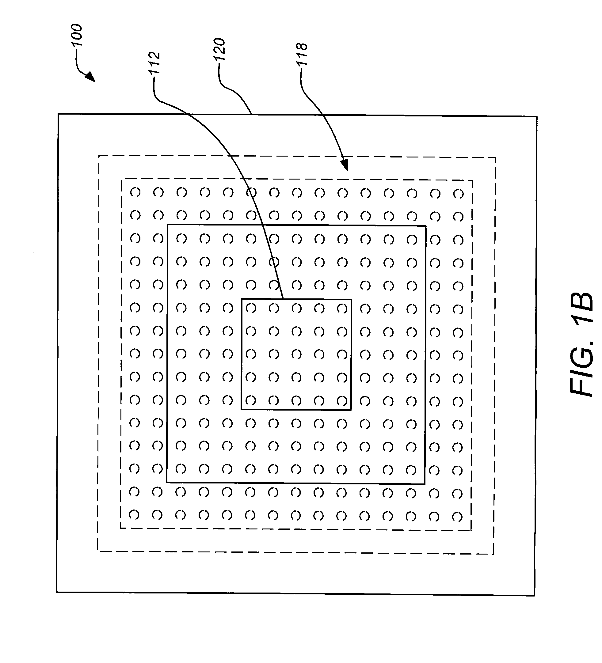
[0025]As previously mentioned, embodiments of the invention are directed to an encapsulated inert non-conductive fluid used to transfer heat directly from an electrical circuit to an external heat-sink. The top of a chip die is enclosed with a metallic cover. The cover is sealed to an outer frame, which in turn is sealed to metallization on the top of the chip through a flexure, minimizing mechanical load into the chip. This forms a hermetic cavity in which the circuit of the chip resides. This cavity is filled with an inert non conductive fluid, which vaporizes when heated. Condensation occurs on the metal cover where the heat is transported into the outer frame for rejection into the spacecraft. Embodiments of the invention provide more efficient cooling than conventional heat-sinks. In addition, embodiments of the invention may be readily implemented with known chip types and retrofitted to existing circuits.

[0026]Embodiments of the invention generally require a ...


PUM


Abstract

An apparatus and method for cooling electronics is disclosed. An encapsulated inert non-conductive fluid is used to transfer heat directly from an electrical circuit including a die on a substrate to an external heatsink. The top of a flip chip die (e.g. a ceramic column grid array flip chip) may be enclosed with a metallic cover. The metallic cover is sealed to an outer frame, which in turn is sealed to metallization on the top of the flip chip through a flexure, minimizing mechanical load imparted to the flip chip. This forms a hermetic cavity enclosing the die. This hermetic cavity is partially filled with an inert non conductive fluid, which vaporizes when heated. Condensation occurs on the inner surface of the metal cover where the heat may be conducted into the outer frame for removal (e.g. rejection from the spacecraft).

Description

BACKGROUND OF THE INVENTION[0001]1. Field of the Invention[0002]This invention relates to heat dissipation in electrical circuits. Particularly, this invention relates heat dissipation in electrical circuits for space applications.[0003]2. Description of the Related Art[0004]In electrical circuits for space applications and generally, heat dissipation requirements tend to increase with more capable electronics. Conventional designs commonly employ heat-sinks mechanically fastened to the die, i.e. bonded to the die and local area of a printed wiring board (PWB), or vias under an ASIC and removed from the die heat-source. However, these designs commonly result in multiple thermal choke points. Thus, improving performance with conventional techniques requires updating design at multiple thermal interfaces. High performance thermal bonds are required, as well as a highly conductive but mechanically compliant heat-sink material. As the power dissipation increases much more area is requir...

Claims


Application Information

Patent Timeline
Patent Type & Authority Applications(United States)
IPC IPC(8): H05K7/20
CPCH01L23/427H05K1/0203H05K2201/064H05K2201/10371H05K2201/10734H01L2924/0002H05K2201/2018H05K2203/083H01L2924/00
Inventor MINDOCK, ERIC S.SCOTT, JOHN R.
Owner THE BOEING CO
Why Eureka
Try Eureka