Bead weaving loom

Active Publication Date: 2016-06-16
M & G PARTNERS
View PDF30 Cites 5 Cited by
  • Summary
  • Abstract
  • Description
  • Claims
  • Application Information

AI Technical Summary

Benefits of technology

[0005]The above considerations, and others, are addressed by the present invention, which can be understood by referring to the specification, drawings, and claims. Disclosed herein is a user-friendly bead weaving loom with a unique design that makes it easier to set up than weaving bead looms currently on the

Problems solved by technology

Existing bead weaving looms do not accommodate combs of differing sizes or configurations

Method used


Image

  • Bead weaving loom
  • Bead weaving loom
  • Bead weaving loom

Examples


Embodiment Construction

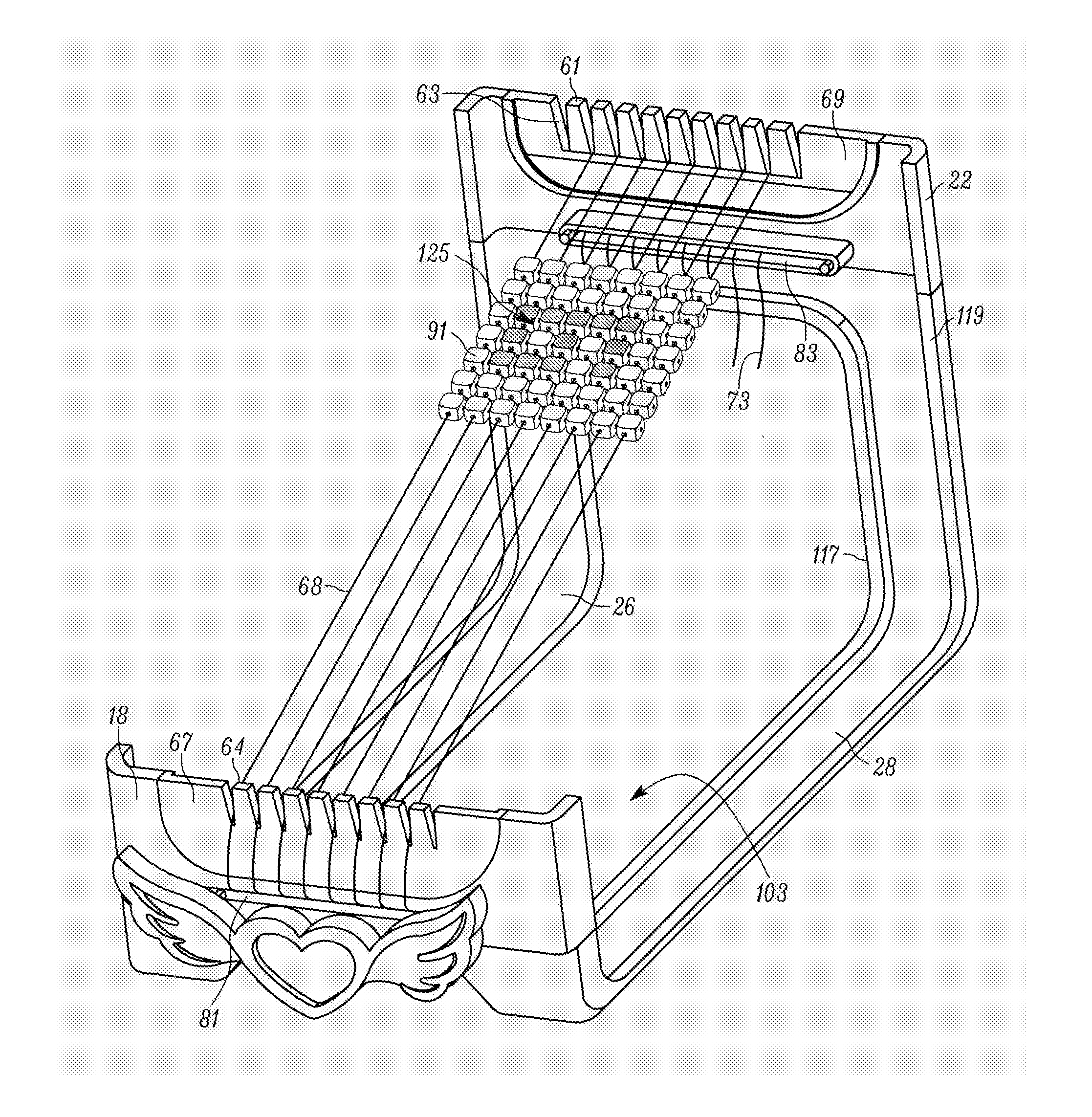
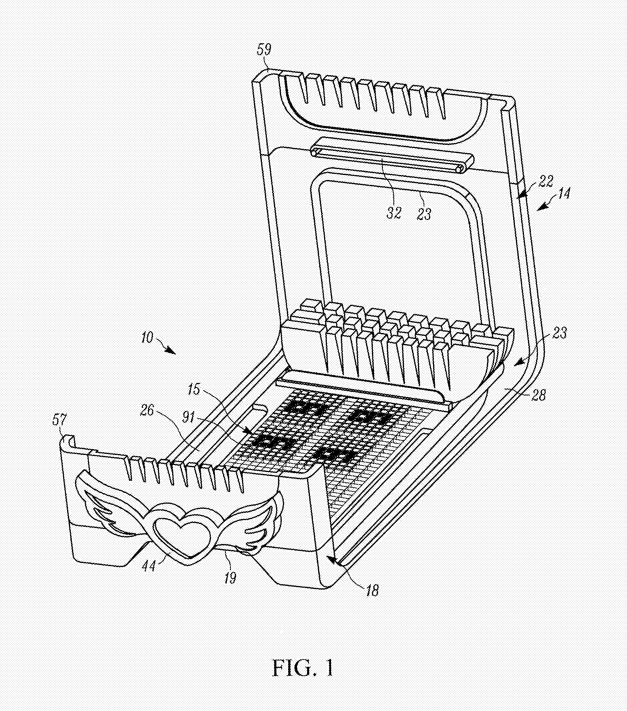
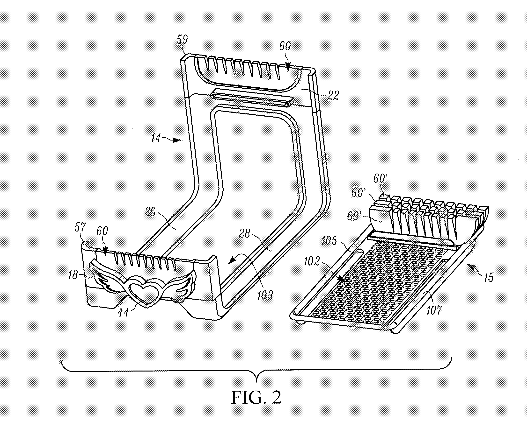
[0018]Reference will now be made in detail to exemplary aspects of the present invention which are illustrated in the accompanying drawings showing illustrative embodiments. Referring to FIGS. 1 and 2, a weave loom 10 is provided that includes a frame 14 and a tray (i.e., bead and comb holder) 15. The frame 14 has a short front wall 18, a rear wall 22 that is taller than the front wall 18, and opposing frame legs 26 and 28 connected between the front wall 18 and the rear wall 22, which together form the frame 14. The front wall 18 includes a front wall base 19 and a front wall top portion 57. The rear wall 22 includes a rear wall base 23 and a rear wall top portion 59. The frame 14, and the tray 15 are molded from a durable lightweight plastic, but other materials could be used in addition to or in place of plastic. As shown in FIG. 3, each wall 18 and 22 has a respective slot 32, and a comb receiving indentation 36 (e.g., cut out), as further described below.

[0019]Further referring...


PUM


Abstract

A bead weaving loom includes a weave frame with a front wall connected to a rear wall by a plurality of frame legs, and a tray having a plurality of bead receiving cavities for receiving a plurality of beads, wherein the tray may be removably situated on the frame.

Description

CROSS REFERENCE TO RELATED APPLICATIONS[0001]The present application claims priority to U.S. Provisional Patent Application No. 62 / 092,705 titled BEAD WEAVING LOOM, filed on Dec. 16, 2014, which is herein incorporated by reference in its entirety.FIELD OF THE INVENTION[0002]The present invention relates generally to the field of weaving looms. More particularly, the invention relates to a portable weaving loom which can be used for hand weaving beaded bands.BACKGROUND[0003]Portable bead weaving looms are used for hand weaving, particularly the weaving of beaded bands and the like which may be made into various articles such as belts, bags, purses and like items. The purpose of the loom is to hold longitudinally extending threads (called “warps”) in spaced relation while threading beads on cross threads (called “wefts”) in a known manner to form a beaded band or other product. Most beading looms in the current market are set up by first wrapping one end of the warp thread around a sc...

Claims


Application Information

Patent Timeline
IPC IPC(8): D03D29/00
CPCD03D29/00D03D15/69
Inventor MILLER, MARKMILLER, GOLDIMOULOUDJI, MYRA
Owner M & G PARTNERS
Why Eureka
Try Eureka