Method and apparatus for adjusting loss caused by optical fiber curvature, and optical transmission system using the same

Inactive Publication Date: 2007-08-16
NEC CORP
View PDF3 Cites 2 Cited by
  • Summary
  • Abstract
  • Description
  • Claims
  • Application Information

AI Technical Summary

Benefits of technology

[0017] As described above, according to the present invention, an optical fiber is wound along the space between the cylindrical interior wall and the plurality of cylindrical optical-fiber support members, whereby the optical fiber is brought in point contact with the optical-fiber support members. Accordingly, the occurrence of a microbend can be prevented. Moreover, since the optical fiber can be led in/out between any adjacent ones of the optical-fiber support members with no stress imposed, the inlet and outlet positions can be easily set. Accordingly, a fine adjustment of an optical loss is possible.
[0018] Further, according to the present invention, at least one insulator is provided above the lower support, whereby loss adjustments can be simultaneously made for a plurality of different optical fibers, respectively. Therefore, if this is applied to an optical multiplexer/demultiplexer for wavelength division multiplexing transmission, the efficiency of installati

Problems solved by technology

However, although this loss increase splicing ensures the quality of transmission on one hand, an expensive optical fiber fusion splicer is needed, as well as many hou

Method used


Image

  • Method and apparatus for adjusting loss caused by optical fiber curvature, and optical transmission system using the same
  • Method and apparatus for adjusting loss caused by optical fiber curvature, and optical transmission system using the same
  • Method and apparatus for adjusting loss caused by optical fiber curvature, and optical transmission system using the same

Examples


first embodiment

1. First Embodiment

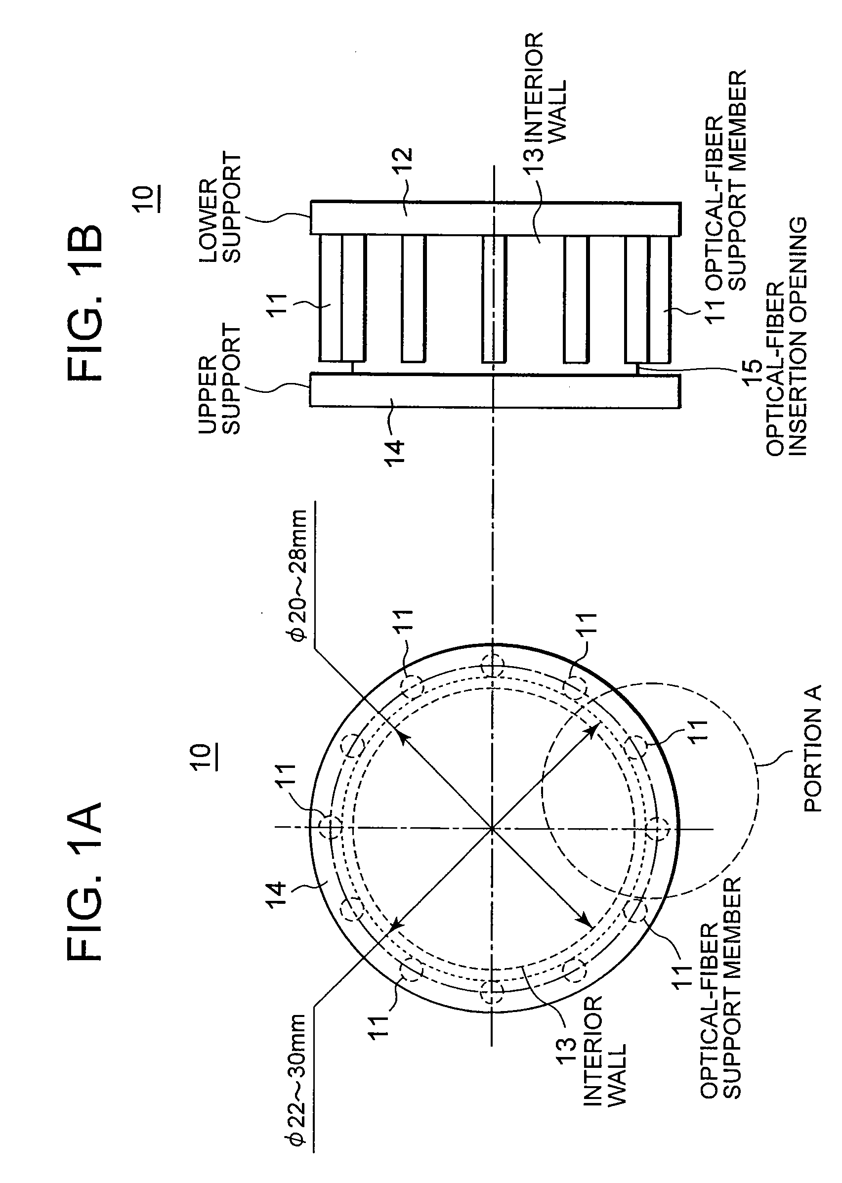
[0029] Referring to FIGS. 1A and 1B, in an optical-fiber loss adjustor 10, a plurality of cylindrical optical-fiber support members 11 are fixed onto a disk-shaped lower support 12, arranged in a circle on the outside of (around) a cylindrical interior wall 13 with a diameter of, for example, 20 to 28 mm. The optical-fiber support members 11 are arranged in a circle which a radius set in the range of 10 to 15 mm. Moreover, the height of the interior wall 13 is set larger than that of the optical-fiber support members 11 by an amount allowing an optical fiber to pass through an optical-fiber insertion opening 15 in FIG. 1B. A disk-shaped upper support 14 is placed and fixed onto the top of the interior wall 13. The upper support 14, interior wall 13 and optical-fiber support members 11 are concentrically disposed.

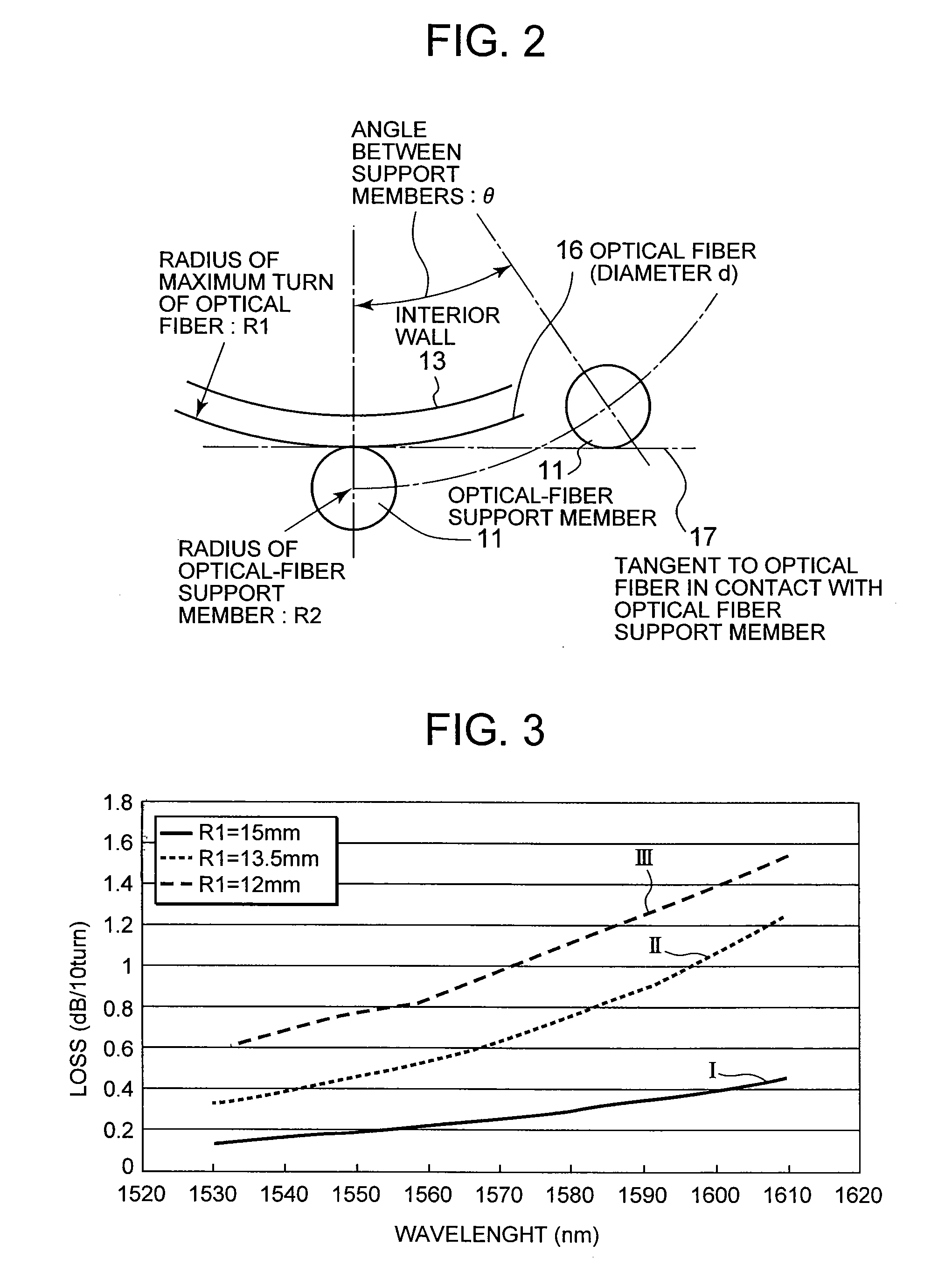
[0030] Referring to FIG. 2, an optical fiber 16 with a diameter d is present between the interior wall 13 and the optical-fiber support members 11. A tan...

second embodiment

2. Second Embodiment

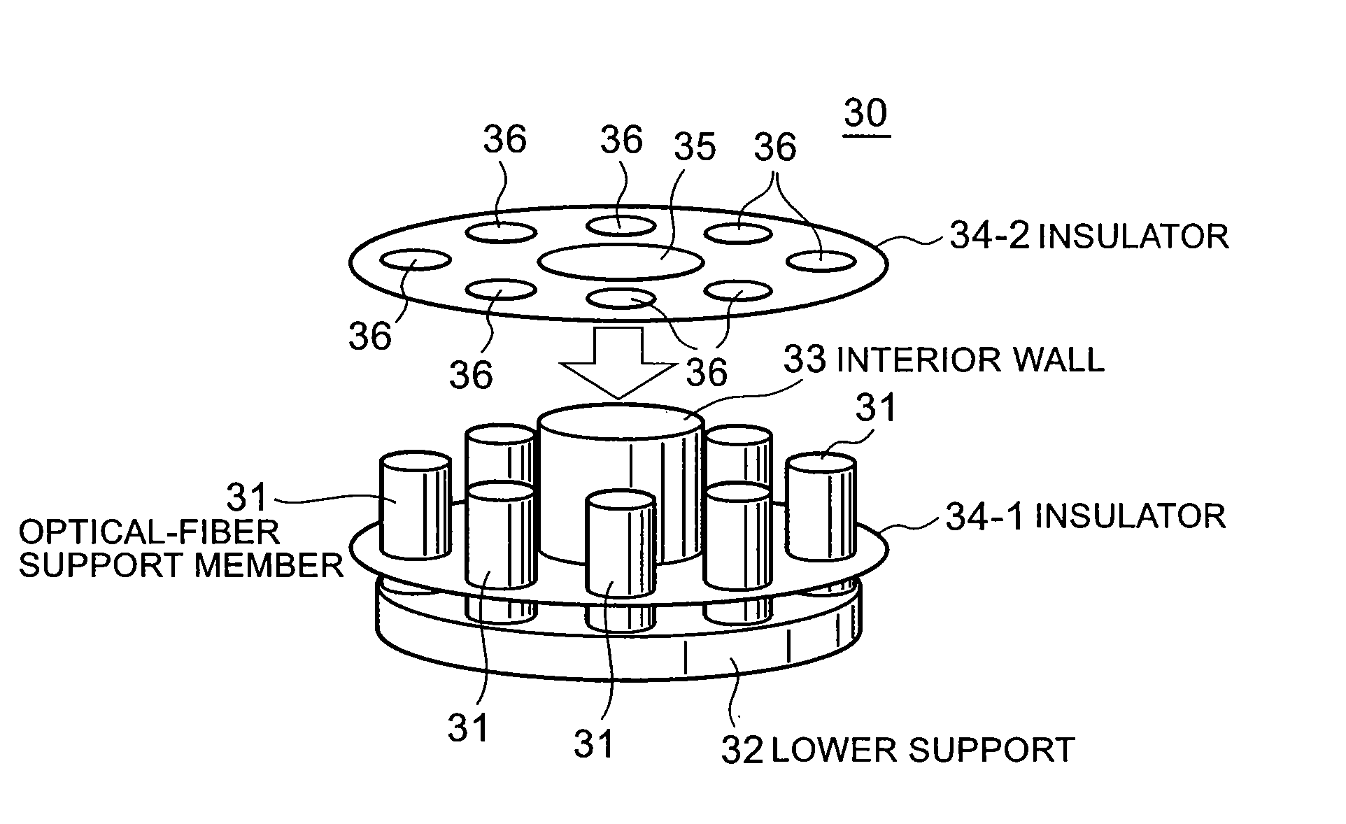
[0046] In the case of applying the present invention to an optical multiplexer / demultiplexer for wavelength division multiplexing (WDM) transmission, since there are a very large number of places where loss adjustment should be carried out, it is impractical, in view of the efficiency of implementation, to individually apply the structure of the first embodiment to each optical fiber. Therefore, according to a second embodiment, a structure is made such that a plurality of optical fibers can be wound in a stacked manner in the height direction, with an insulator interposed between each optical fiber.

[0047] Referring to FIGS. 5 and 6, in an optical-fiber loss adjustor according to the second embodiment of the present invention, the height of each optical-fiber support member 31 is set as large as a plurality of optical fibers can be stacked and each wound around a circle composed of a plurality of optical-fiber support members 31. Except this point, the second em...

third embodiment

3. Third Embodiment

[0050] A third embodiment of the present invention is a structure in which a bobbin for optical fiber accommodation and loss adjusting means according to the present invention are integrated. This structure can provide space savings.

[0051] Referring to FIG. 7, an optical-fiber loss adjustor 40 according to the third embodiment, provided with loss adjusting means and an extra fiber length management portion, is structured as follows. Specifically, as the loss adjusting means, a cylindrical interior wall 42 is disposed and fixed onto a lower support, and a plurality of cylindrical optical-fiber support members 41 with a small diameter are concentrically disposed so as to surround the interior wall 42. The extra fiber length management portion in a cylindrical shape is provided at the outmost periphery. Fiber guides 43 are appropriately arranged around the optical-fiber support members 41 so that an optical fiber can be smoothly routed between these concentrically d...


PUM


Abstract

The present invention achieves highly reliable optical-fiber loss adjustment at low cost, with easy work. An optical fiber is inserted from an optical fiber insertion opening into a space between an internal wall and a plurality of optical-fiber support members and, due to its self-resilience, comes in contact with the support members on its outer side. Since the radius of curvature of the fiber is sufficiently small, a loss can be adjusted with the number of turns of the fiber. The support members have a cylindrical shape and therefore come in point contact with the fiber, which can prevent microbending. Moreover, the interval (angle) between adjacent ones of the support members and the radius thereof are set such that the fiber can be led into and out of an optical-fiber adjustor, with no stress imposed.

Description

BACKGROUND OF THE INVENTION [0001] 1. Field of the Invention [0002] The present invention relates to techniques for adjusting the loss or attenuation caused by the curvature of an optical fiber and, more particularly, to a method and an apparatus for adjusting an intensity loss of an optical signal transmitted through the optical fiber, as well as to an optical transmission system using the same. [0003] 2. Description of the Related Art [0004] In a multiple-relay wavelength division multiplexing transmission system, a large number of optical multiplexers / demultiplexers, optical amplifiers and the like are used. These optical devices are constituted in such a manner that two or more optical components are connected by fiber fusion splicing. To prevent variations in loss among multiple principal signals, adopted is loss increase splicing, which intentionally gives a loss. [0005] To accomplish this intentional increase of a loss, generally employed is a method by which the cores of spl...

Claims


Application Information

Patent Timeline
IPC IPC(8): G02B6/00
CPCG02B6/4457G02B6/266
Inventor OGUMA, TAKEFUMI
Owner NEC CORP
Why Eureka
Try Eureka