LC (launch complex) simple harmonic oscillating circuit and sinusoidal signal generator thereof
A simple harmonic oscillation and circuit technology, applied in the field of LC simple harmonic oscillation circuit and its sine signal generator, can solve the problems of complex structure of LC oscillator, difficult parameter design and setting, large distortion of output sine wave, etc., and achieves wide practicality. Value, convenient parameter setting, good performance effect
- Summary
- Abstract
- Description
- Claims
- Application Information
AI Technical Summary
Problems solved by technology
Method used
Image
Examples
Embodiment 1
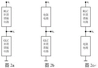
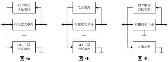
[0052] The basic series-parallel dual-resonance structure LC simple harmonic oscillation circuit such as Figure 6 As shown, the series-parallel double resonance structure LC resonance voltage divider circuit and the amplifier circuit form a closed loop to form an LC simple harmonic oscillation circuit.
[0053] Amplifying circuit consists of operational amplifier A0 and resistor R 01 , R 02 Composition, the voltage magnification is:
[0054] A u = 1 + R 02 R 01 = R 01 + R 02 R 01
[0055] The series-parallel double-resonant structure LC resonant voltage divider circuit consists of an RLC series resonant circuit and a GLC parallel resonant circuit, and the GLC parallel resonant circuit consists of a ...
Embodiment 2
[0077] A typical series-parallel double resonance structure LC simple harmonic oscillation circuit such as Figure 9 As shown, the series-parallel double resonance structure LC resonance voltage divider circuit and the amplifier circuit form a closed loop to form an LC simple harmonic oscillation circuit.
[0078] The series-parallel double-resonant structure LC resonant voltage divider circuit consists of an RLC series resonant circuit and a GLC parallel resonant circuit, and the GLC parallel resonant circuit consists of a conductance G 11 , inductance L 1 , capacitance C 1 It is formed in parallel, and the RLC series resonant circuit is composed of resistor R 12 , inductance L 1 , capacitance C 1 formed in series. The transfer function of the LC resonant voltage divider circuit is:
[0079] F u = 1 ...
Embodiment 3
[0102] Negative temperature coefficient thermistor starts oscillation and stabilizes amplitude series-parallel double resonance structure LC simple harmonic oscillation circuit such as Figure 12 As shown, the series-parallel double resonance structure LC resonance voltage divider circuit and the amplifier circuit form a closed loop to form an LC simple harmonic oscillation circuit.
[0103] when: , the LC resonant voltage divider circuit is in a resonant state, and the voltage division coefficient of the LC resonant voltage divider circuit reaches the maximum value at this time:
[0104] F u 0 = 1 1 + G 1 R 1 = 1 2
[0105] in:
[0106] Amplifying circuit consists of operational amplifier A0 and resistor R 01 , Potentiometer R P0 , NTC thermist...
PUM
 Abstract
Description
Claims
Application Information
 - R&D
- Intellectual Property
- Life Sciences
- Materials
- Tech Scout
- Unparalleled Data Quality
- Higher Quality Content
- 60% Fewer Hallucinations
Browse by: Latest US Patents, China's latest patents, Technical Efficacy Thesaurus, Application Domain, Technology Topic, Popular Technical Reports.
© 2025 PatSnap. All rights reserved.Legal|Privacy policy|Modern Slavery Act Transparency Statement|Sitemap|About US| Contact US: help@patsnap.com


