Multi-flute ball end mill

a ball end mill and multi-flute technology, applied in the direction of metal-working equipment, milling equipment, metal-working apparatus, etc., can solve the problems of affecting the speed affecting the efficiency of the ball end mill, and generating vibration, so as to reduce the speed and breakage. , the effect of suppressing vibration

Active Publication Date: 2016-06-23
HITACHI TOOL ENG LTD
View PDF10 Cites 15 Cited by
  • Summary
  • Abstract
  • Description
  • Claims
  • Application Information

AI Technical Summary

Benefits of technology

[0014]It is preferable that each center-lowered, inclined cutting edge has at least an arcuate portion projecting rearward in a rotation direction; that the arcuate portion has a curvature (ratio of the length of a perpendicular line extending from an apex of the arcuate portion to a line connecting both ends of the arcuate portion to the length of a line connecting both ends of the arcuate portion) of 5-40%; and that each center-lowered, inclined cutting edge is inclined with an inclination angle α of 0.5-3° relative to a plane perpendicular to the rotation axis, such that the rotation center point is positioned on the rear side of a connecting point of each center-lowered, inclined cutting edge and each ball-end cutting edge in a rotation axis direction.

Problems solved by technology

In the cutting of a work by a ball end mill, however, a large load is applied to portions of ball-end cutting edges near a rotation center point, in which a rotation speed is substantially zero, thereby generating vibration.
As a result, the ball-end cutting edges suffer chipping and breakage near the rotation center point.
Accordingly, when this multi-flute ball end mill is used for high-feed roughing of a high-hardness, difficult-to-cut material, chipping and breakage occur in the ball-end cutting edges and peripheral cutting edges.
However, because this ball end mill does not have cutting edges near the rotation center point, it suffers vibration due to a large load applied near the rotation center point.
Accordingly, when this multi-flute ball end mill is used for high-feed roughing of a high-hardness, difficult-to-cut material, chipping and breakage occur in the ball-end cutting edges and peripheral cutting edges.
However, because ball-end cutting edges and peripheral cutting edges have small twist angles, chipping and breakage cannot be sufficiently prevented in high-feed roughing of a high-hardness, difficult-to-cut material.
However, because this ball end mill does not have center-lowered, inclined cutting edges, the clogging of chips occurs near the rotation center point in high-feed roughing of a high-hardness, difficult-to-cut material.
Also, because the ball-end cutting edges and the peripheral cutting edges have small twist angles, chipping and breakage cannot be sufficiently prevented in high-feed roughing of a high-hardness, difficult-to-cut material.
Also, because a rake face of each peripheral cutting edge largely enters a rake face of each ball-end cutting edge, with each ball-end cutting edge not having a convex rake face, each ball-end cutting edge of this ball end mill has insufficient rigidity and strength.
Accordingly, when this multi-flute ball end mill is used for high-feed roughing of a high-hardness, difficult-to-cut material, chipping and breakage occur in the ball-end cutting edges and peripheral cutting edges.

Method used


Image

  • Multi-flute ball end mill
  • Multi-flute ball end mill
  • Multi-flute ball end mill

Examples


first embodiment

(1) First Embodiment

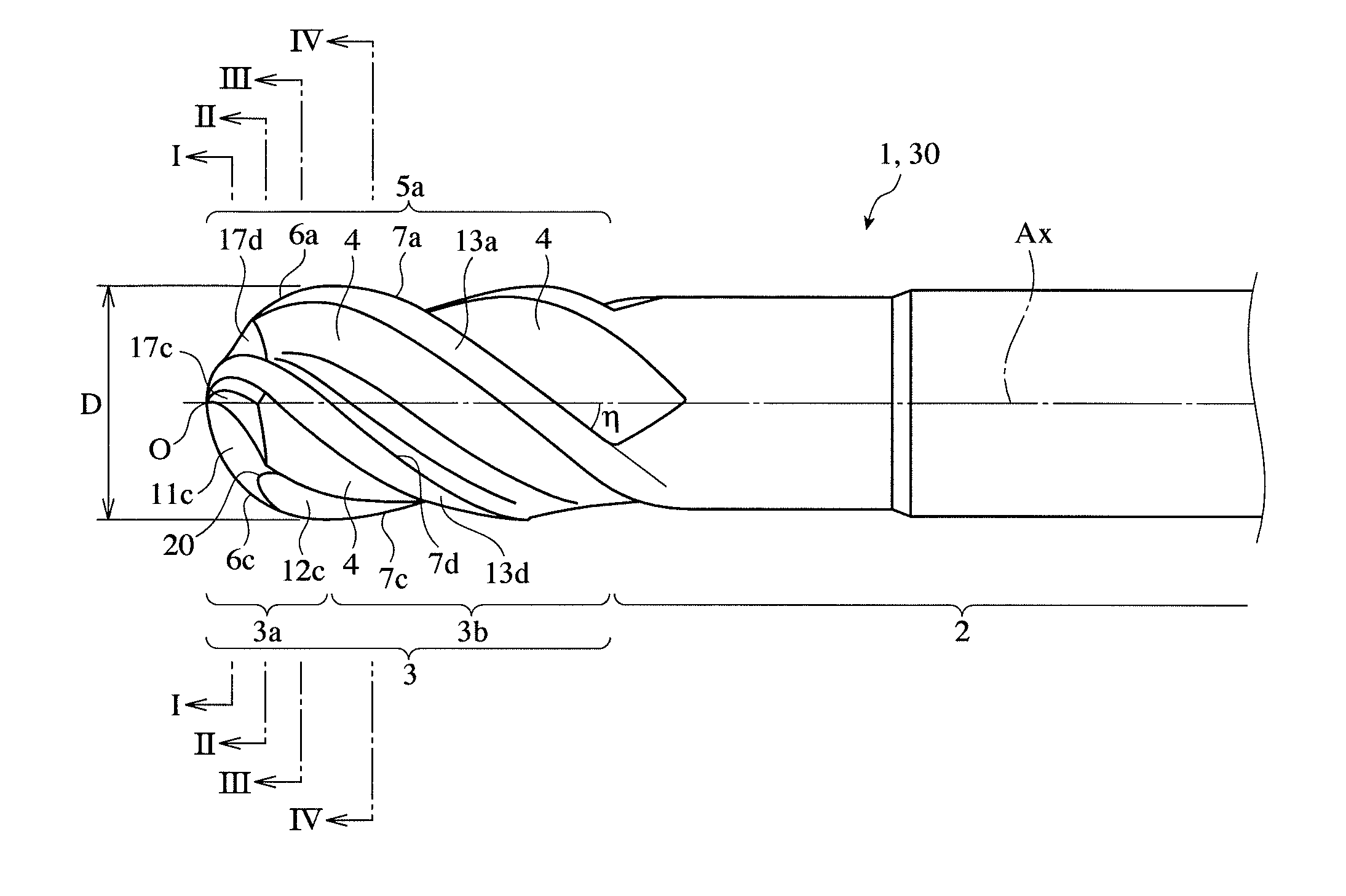
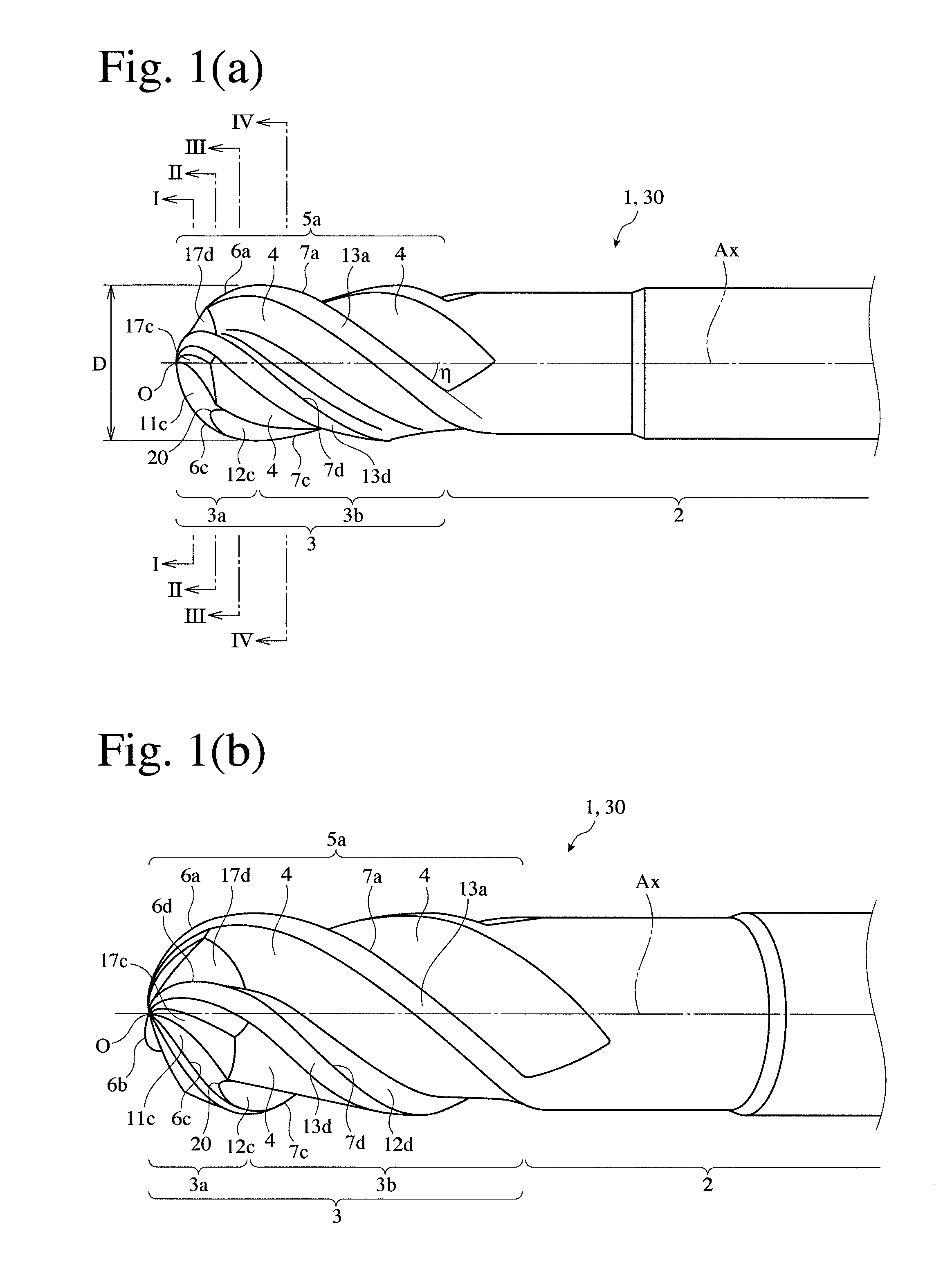
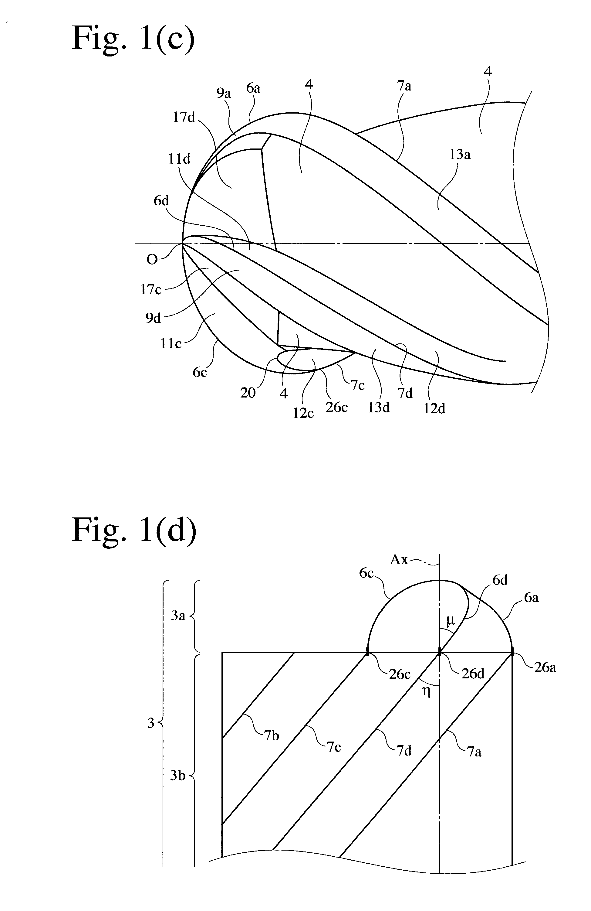
[0067]The four-flute ball end mill 1 according to the first embodiment of the present invention, which is shown in FIGS. 1-7, comprises a cylindrical shank portion 2, and a cutting edge portion 3, which has a tip-end ball portion 3a, and a peripheral cutting edge portion 3b between the ball portion 3a and the shank portion 2. The cutting edge portion 3 is provided with four cutting edges 5a, 5b, 5c, 5d each having a predetermined twist angle. Each cutting edge 5a-5d is constituted by a circular ball-end cutting edge 6a, 6b, 6c, 6d formed in the ball portion 3a, and a spiral peripheral cutting edge 7a, 7b, 7c, 7d formed in the peripheral cutting edge portion 3b, and each ball-end cutting edge 6a-6d is smoothly (with no inflection point) connected to each peripheral cutting edge 7a-7d. As shown in FIG. 2, four ball-end cutting edges 6a-6d are arranged via gashes 17a-17d around a rotation center point O in the ball portion 3a.

[0068]As shown in FIGS. 1(a)-1(c), each...

second embodiment

(2) Second Embodiment

[0088]As shown in FIGS. 8(a) and 8(b), the four-flute ball end mill 30 according to the second embodiment of the present invention is substantially the same as the four-flute ball end mill 1 in the first embodiment, except for the shape of each center-lowered, inclined cutting edge and the uneven arrangement of ball-end cutting edges. In FIG. 8, the same reference numerals are assigned to the same portions as in the first embodiment. These differences will be explained in detail below.

[0089]FIG. 9 enlargedly shows part of FIG. 8(b). An arcuate portion 8c1 obtained by the formation of a flank 10d extends between a rotation center point O and a point K3, and a curved extension 8c2 extending radially inward from a ball-end cutting edge 6c is connected to the arcuate portion 8c1 at the point K3. The point K3 is an inflection point between the arcuate portion 8c1 and the curve portion 8c2.

[0090]In the example shown in FIG. 9, too, the circumferential width W1 of a fl...


PUM


Abstract

A multi-flute ball end mill comprising a shank portion, a cutting edge portion having a ball-shaped tip portion, and 3 or more cutting edges formed in the cutting edge portion; each cutting edge being constituted by a peripheral cutting edge having a twist angle η of 35-45°, and a ball-end cutting edge having a twist angle μ at the outermost peripheral point, the twist angle η and the twist angle μ meeting the relation of η−μ≦7°, such that the ball-end cutting edge is smoothly connected to the peripheral cutting edge; the ball-end cutting edge having a radial rake angle of −37° to −11°; the peripheral cutting edge having a radial rake angle of 2-8°; and a center-lowered, inclined cutting edge integrally extending from a tip end of each ball-end cutting edge to a rotation center point, in a tip end portion of the ball portion near the rotation center point.

Description

FIELD OF THE INVENTION[0001]The present invention relates to a multi-flute ball end mill having a long life with little chipping and breakage, even in high-feed roughing of a high-hardness, difficult-to-cut material such as hardened steel, etc. used for various dies.BACKGROUND OF THE INVENTION[0002]As long-life ball end mills capable of efficiently cutting high-hardness dies used for the production of various parts in automobile industries, electronic industries, etc., multi-flute ball end mills of cemented carbide having 3 or more ball-end cutting edges are widely used. In the cutting of a work by a ball end mill, however, a large load is applied to portions of ball-end cutting edges near a rotation center point, in which a rotation speed is substantially zero, thereby generating vibration. As a result, the ball-end cutting edges suffer chipping and breakage near the rotation center point. To solve this problem, various proposals have been made so far.[0003]JP 2002-187011 A propose...

Claims


Application Information

Patent Timeline
Patent Type & Authority Applications(United States)
IPC IPC(8): B23C5/10
CPCB23C5/1009B23C2210/0428B23C2210/205B23C2210/0435B23C2210/0457B23C2210/40B23C2210/202B23C2210/203B23C2210/204B23C2210/54B23C2210/0485
Inventor SAKAI, SHINJIROH
Owner HITACHI TOOL ENG LTD
Why Eureka
Try Eureka