
Brake actuator for aircraft wheel hydraulic brake

a technology of hydraulic brake and brake actuator, which is applied in the direction of fluid actuated brake, aircraft braking arrangement, hoisting equipment, etc., can solve the problems of piston seal wear, actuator leakage, and element wear gradually

Inactive Publication Date: 2016-06-23
SAFRAN LANDING SYSTEMS
View PDF10 Cites 13 Cited by
  • Summary
  • Abstract
  • Description
  • Claims
  • Application Information

AI Technical Summary

Benefits of technology

The invention proposes a brake actuator for an aircraft hydraulic brake that avoids wear of friction materials and prevents damage to the brake ring. It includes a liner, a piston, a wear compensation device, and an elastic return member. The mobile stop of the actuator is associated with a notched indexing member which allows the mobile stop to move under the thrust of the piston but prevents any return motion of the mobile stop. This prevents wear and damage to the brake ring and ensures the actuator's seal integrity even in polluted environments. The notched indexing member comprises a notched wall and a deformable ring with a notched portion and a conical seat.

Problems solved by technology

However, the friction elements gradually become worn as a result of repeated application of braking forces so it is important to ensure that the piston is always near the friction elements.
In certain circumstances, it has been observed that, in those regions of the liner against which bears the friction member associated with the mobile stop, the piston seal could wear more rapidly, which reduces the leaktightness of the actuator.

Method used


Image

  • Brake actuator for aircraft wheel hydraulic brake
  • Brake actuator for aircraft wheel hydraulic brake
  • Brake actuator for aircraft wheel hydraulic brake

Examples


Embodiment Construction

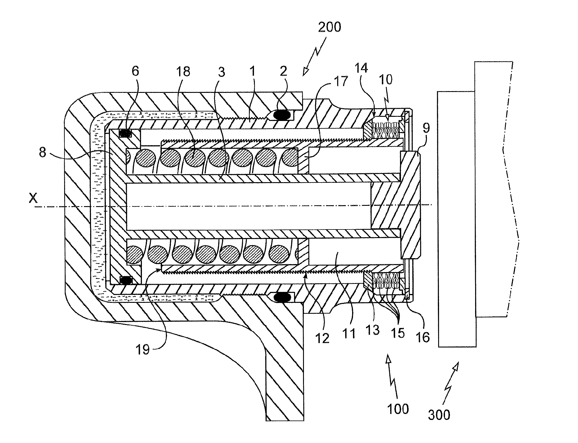
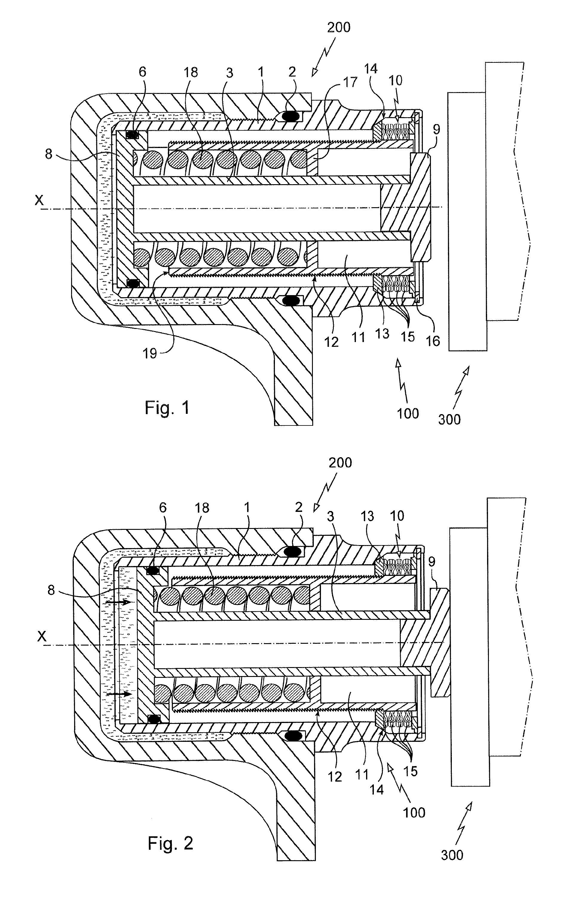
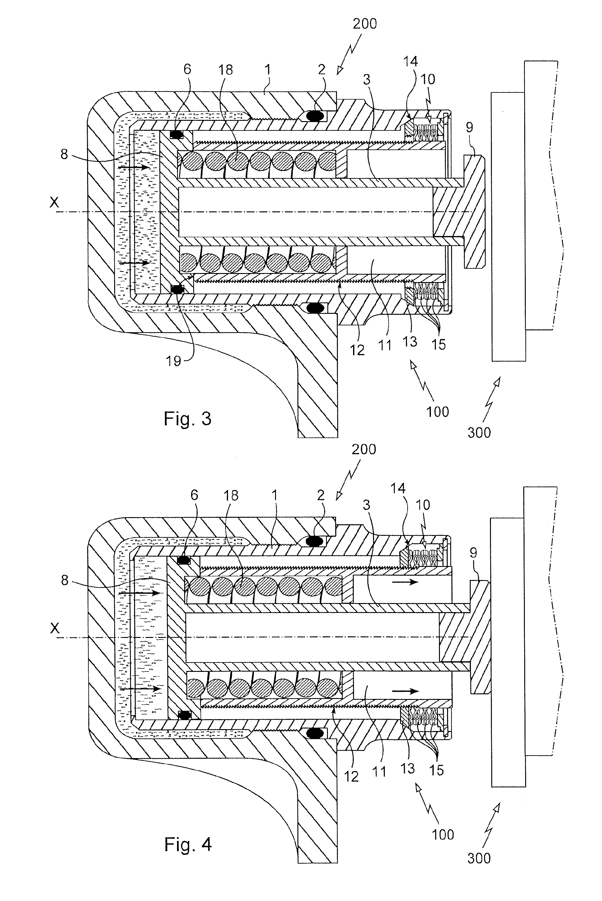
[0026]With reference to FIG. 1, the brake actuator 100 of the invention is intended to be housed in one of the cavities 200 of a ring of an aircraft hydraulic brake, which moreover comprises friction elements 300 comprising a succession of rotor discs and stator discs, for example discs made of carbon, on which the actuator selectively applies a braking force when pressurized fluid (illustrated as dots) is admitted to the cavity 200.

[0027]The actuator 100 first of all comprises a generally cylindrical liner 1 which is housed sealingly inside the cavity 200 of the ring. For that purpose, a seal 2 collaborates with an external face of the liner to contain the hydraulic fluid within the cavity.

[0028]A piston 3 is mounted to slide in the liner 1 along an axis of sliding X. To that end, the piston 3 comprises a proximal end 8 that is shaped like a bearing which fits closely against an internal face of the liner 1 and which receives a seal 6.

[0029]It will be noted that the proximal end 8 ...


PUM


Abstract

The invention relates to a brake actuator for an aircraft hydraulic brake, which is intended to be added into one of the cavities of a brake ring, the actuator comprising:a liner (1) designed to be housed sealingly in the cavity of the ring;a piston (3) mounted to slide sealingly in the liner along an axis of sliding so as to apply a braking force when a fluid is introduced under pressure into the cavity;a wear compensation device (10) which defines a position to which the piston retreats into the liner by means of a mobile stop (11; 111) that can be moved forward by the piston as a braking force is applied;an elastic return member (18) returning the piston towards the retracted position bearing against the mobile stop;according to the invention, the mobile stop is associated with a notched indexing member (13) allowing the mobile stop to move under the thrust of the piston, but preventing any return motion of the mobile stop with respect to the liner.

Description

[0001]The invention relates to a brake actuator for an aircraft wheel hydraulic brake.TECHNICAL BACKGROUND OF THE INVENTION[0002]The hydraulic brakes used for braking the wheels of aircraft generally comprise a ring having multiple cavities in which brake actuators are housed removably. Each of the actuators comprises a liner which is sealingly added to one of the cavities of the ring and in which a piston is mounted to slide sealingly along an axis of sliding. The ring distributes hydraulic fluid under pressure to all its cavities, which fluid acts on the piston in order to cause it to deploy and apply a braking force to friction elements extending opposite the ring, including rotors which rotate with the wheels and stators which are prevented from rotating.[0003]In general, the piston has an operational travel that it covers when a braking force is applied. This operational travel, of the order of a few millimetres, is enough to allow the braking force to be applied to the frictio...

Claims


Application Information

Patent Timeline
Patent Type & Authority Applications(United States)
IPC IPC(8): B64C25/44F16D65/74F16D55/41F16D65/18
CPCB64C25/44F16D65/18F16D2121/04F16D55/41F16D65/74B60T7/108F16D65/52
Inventor EYANGA, VICTORGONZALEZ, VINCENT
Owner SAFRAN LANDING SYSTEMS
Learn More