Mandibular advancement device

a mandibular and device technology, applied in the field of medical devices, can solve the problems of limited ability to consistently and precisely transfer the prescription into the device design, need for additional adjustments, and many limitations of the existing sleep apnea device, and achieve the effect of reducing the partial constriction of the airway

Active Publication Date: 2016-06-30
PROSOMNUS SLEEP TECH INC
View PDF9 Cites 43 Cited by
  • Summary
  • Abstract
  • Description
  • Claims
  • Application Information

AI Technical Summary

Benefits of technology

[0008]Disclosed herein are mandibular advancement devices comprising an upper splint and a lower splint, where the upper splint comprises one or more upper fins, where each upper fin is located at a distance UD from back of the upper splint; the lower splints comprise one or more lower fins, where each lower fin is located at a distance LD from back of the lower splint; where the position of the upper and lower fins is unchangeable. Also disclosed are methods of reducing partial constriction of airway during sleep for a patient, the method comprising identifying a patient in need thereof; and administering to the patient the disclosed mandibular advancement device. Also disclosed are methods of manufacturing a mandibular advancement device, the method comprising obtaining measurements from a patient's dentition; digitally designing a mandibular advancement device; and milling the mandibular advancement device. Also disclosed are methods of selecting a mandibular advancement device for a patient, the method comprising a) obtaining two or more upper splints of the mandibular

Problems solved by technology

Several limitations exist with these existing sleep apnea devices.
First, the manual, artisanal fabrication method used by these devices limits the ability to consistently and precisely transfer the prescription into the device design.
This limitation results in the need for additional adjustments.
Second, the manual artisanal fabrication method requires the layering of monomers, which can subject the patient to higher levels of r

Method used


Image

  • Mandibular advancement device
  • Mandibular advancement device
  • Mandibular advancement device

Examples


Embodiment Construction

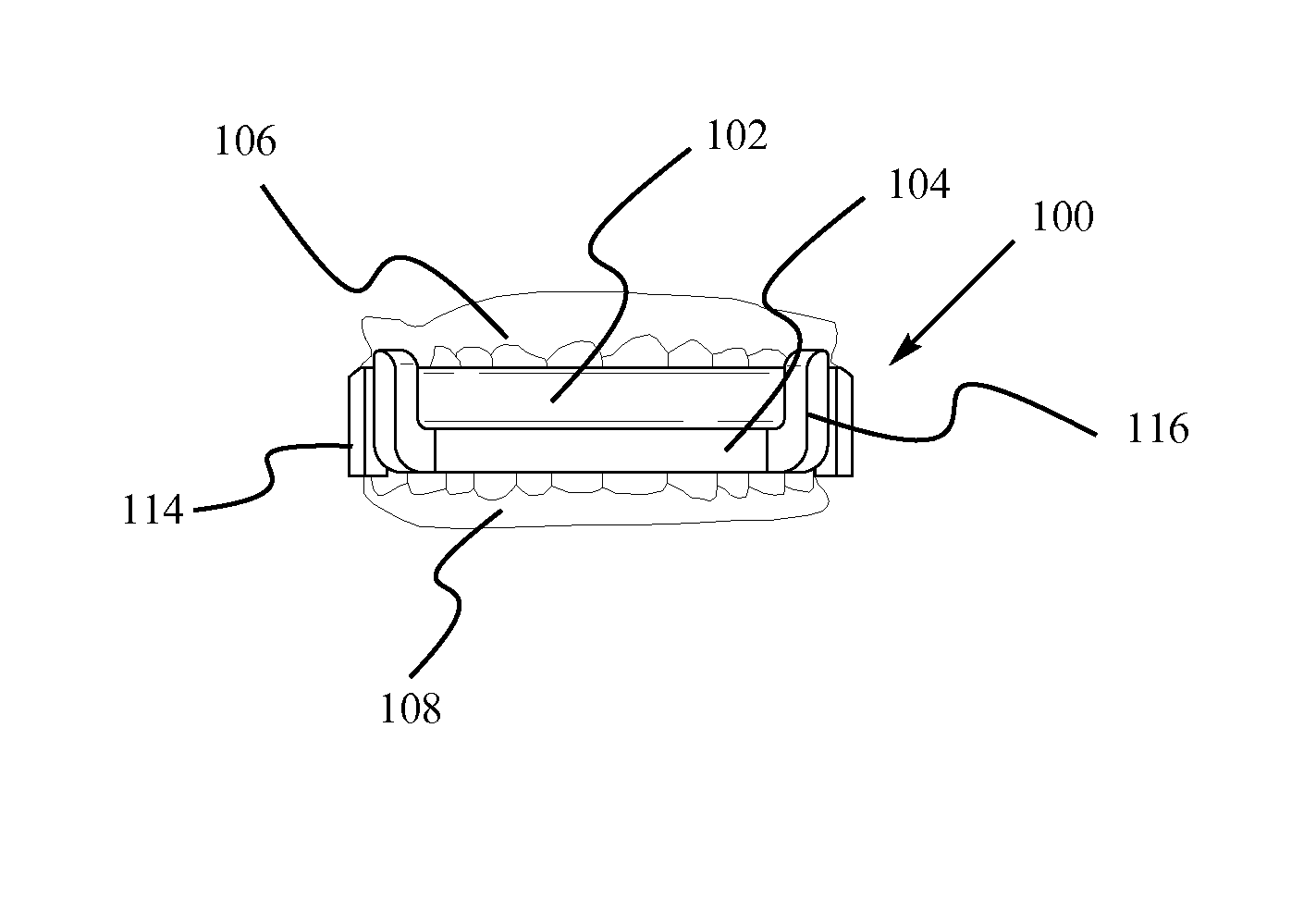
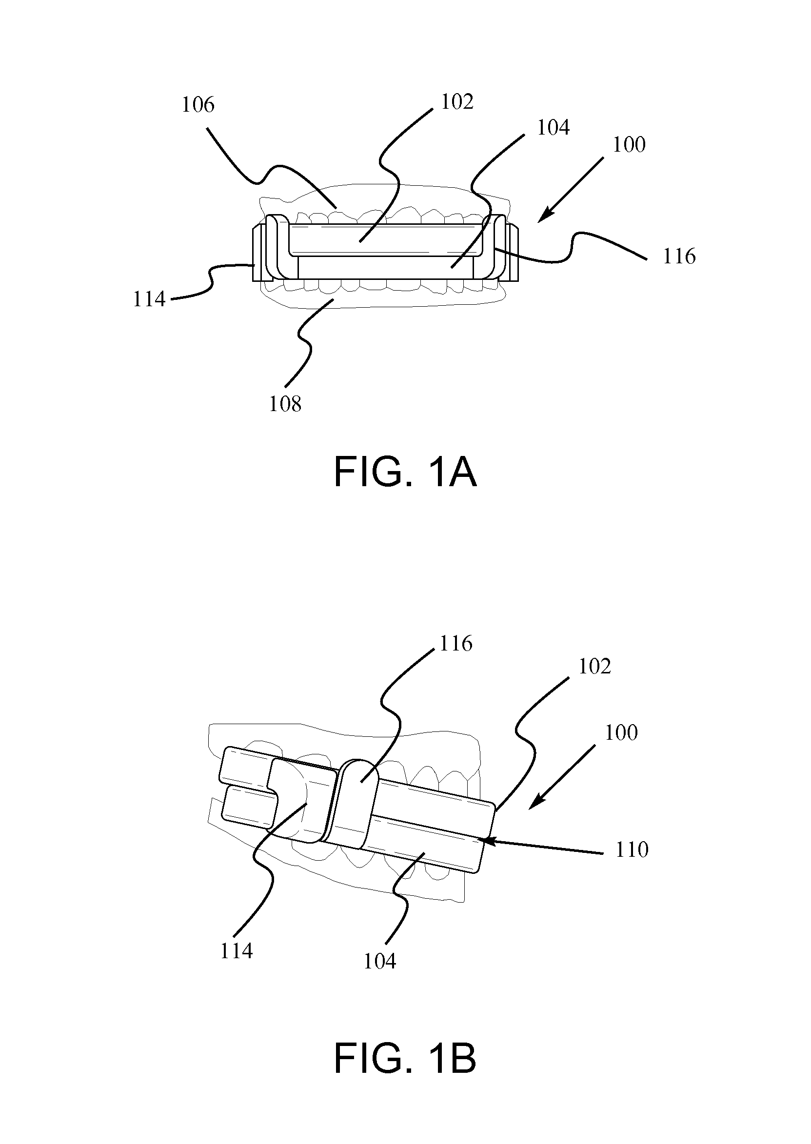
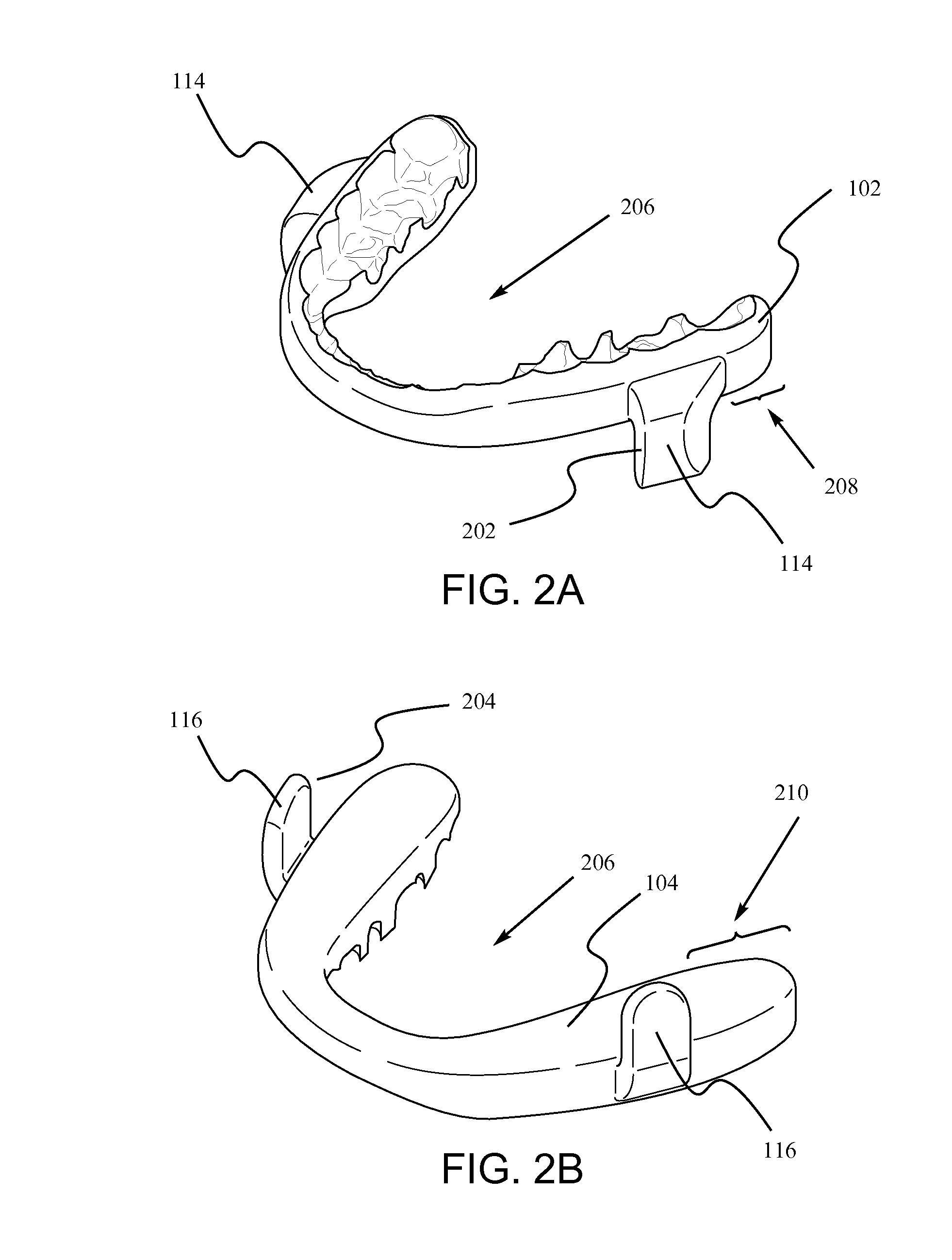
[0017]In one aspect provided herein is a digitally designed and milled mandibular advancement device comprising an upper splint and a lower splint, wherein the upper and lower splints independently further comprise one or more fins. In some embodiments, the splints provide accurate increments of advancement of the lower jaw for titration of the mandible. The terms “dental splint” and “splint” as used herein refers to several types of orthodontic devices that are designed to address dental problems such as loose teeth and bruxism, in addition to problems with snoring and apnea.

[0018]A patient in need of the disclosed mandibular advancement devices wears the upper splint on the upper dentition and the lower splint on the lower dentition during sleep. The splints are designed to remain attached to the dentition until the patient removes them. The fins of the upper and lower splints cause a precise placement of the mandible in relation to the maxilla. The mandible is caused to stay in a...


PUM


Abstract

Disclosed herein are mandibular advancement devices comprising an upper splint and a lower splint, where the upper splint comprises one or more upper fins, where each upper fin is located at a distance UD from back of the upper splint; the lower splints comprise one or more lower fins, where each lower fin is located at a distance LD from back of the lower splint; where the position of the upper and lower fins is unchangeable. Also disclosed are methods of reducing partial constriction of airway during sleep for a patient, the method comprising identifying a patient in need thereof; and administering to the patient the disclosed mandibular advancement device. Also disclosed are methods of manufacturing a mandibular advancement device, the method comprising obtaining measurements from a patient's dentition; digitally designing a mandibular advancement device; and milling the mandibular advancement device.

Description

RELATED APPLICATIONS[0001]This application is a continuation of the International Application PCT / US2014 / 072398, filed Dec. 24, 2014, which designates the U.S. and claims priority to the U.S. Provisional Application Ser. No. 61 / 922,016, filed on Dec. 30, 2013, by David Kuhns et al., and entitled “MANDIBULAR ADVANCEMENT DEVICE,” the entire disclosure of both which is incorporated herein by reference, including all the drawings.FIELD OF THE INVENTION[0002]The present invention is in the field of medical devices, and in particular it is in the field of mandibular advancement devices.BACKGROUND OF THE DISCLOSURE[0003]Snoring and mild sleep apnea are generally thought to be the result of a reduced or partial constriction of the airway during sleep. This may be attributed to soft tissue sinking and applying pressure on the airway during sleep including the mandible dropping and moving backwards. Mandibular advancement devices are designed to move the mandible forward to relieve the force ...

Claims


Application Information

Patent Timeline
IPC IPC(8): A61F5/56
CPCA61F5/566A61C7/08A61C7/36B23C3/00B23C2226/61
Inventor LIPTAK, LEONARD A.KUHNS, DAVID W.KIM, SUNGSHEPPARD, LAURA
Owner PROSOMNUS SLEEP TECH INC
Why Eureka
Try Eureka