Trunnion for high-pressure turbine, and turbojet engine including such a trunnion

Active Publication Date: 2016-06-30
SN DETUDE & DE CONSTR DE MOTEURS DAVIATION S N E C M A
View PDF2 Cites 1 Cited by
  • Summary
  • Abstract
  • Description
  • Claims
  • Application Information

AI Technical Summary

Benefits of technology

[0010]This problem is resolved within the scope of the present invention by way of a trunnion for a high-pressure turbine, intended to be disposed between a low-pressure turbine shaft and an inner surface of a seal support of a low-pressure turbine, the trunnion being characterized in that it comprises a drop-launching extension arranged to extend facing a flared portion of the inner surface of the seal support such that when the trunnion is driven in rotation around the low-pressure turbine shaft, oil tending

Problems solved by technology

When such a turbojet engine is operati

Method used


Image

  • Trunnion for high-pressure turbine, and turbojet engine including such a trunnion
  • Trunnion for high-pressure turbine, and turbojet engine including such a trunnion
  • Trunnion for high-pressure turbine, and turbojet engine including such a trunnion

Examples


Embodiment Construction

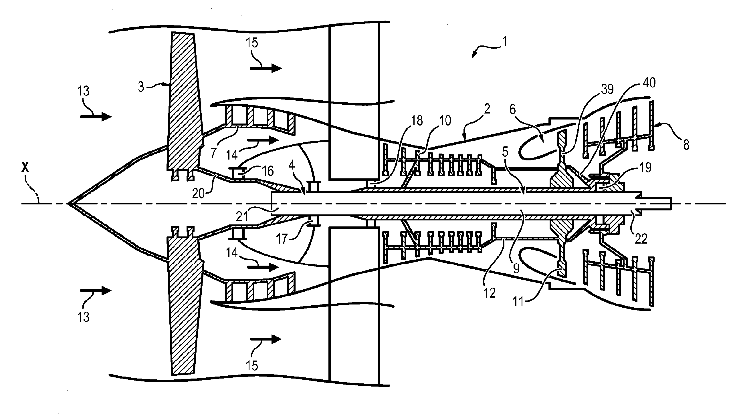
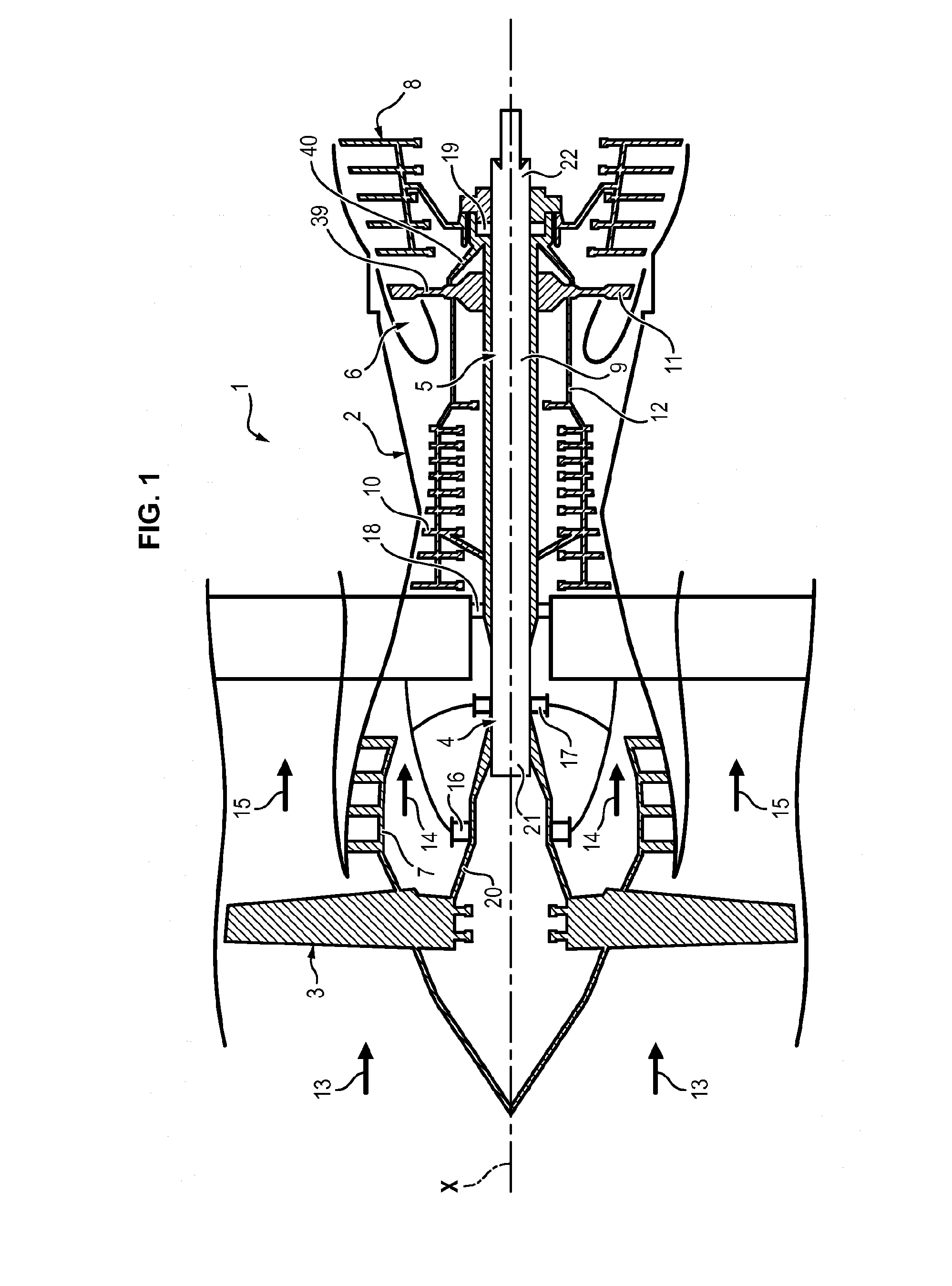
[0025]In FIG. 1, the illustrated turbojet engine 1 comprises a casing 2, a fan 3, a low-pressure body 4, a high-pressure body 5 and a combustion chamber 6.

[0026]The low-pressure body 4 comprises a low-pressure compressor 7, a low-pressure turbine 8 and a low-pressure turbine shaft 9 connecting the low-pressure compressor 7 to the low-pressure turbine 8. The low-pressure turbine shaft 9 extends according to a longitudinal axis X of the turbojet engine 1. The low-pressure turbine 8 is capable of driving the low-pressure compressor 9 in rotation via the low-pressure turbine shaft 9. All of the low-pressure body 4 is then driven in rotation relative to the casing 2 around the axis X.

[0027]The high-pressure body 5 comprises a high-pressure compressor 10, a high-pressure turbine 11 and a high-pressure compressor shaft 12 connecting the high-pressure compressor 10 to the high-pressure turbine 11. The high-pressure compressor shaft 12 extends around the low-pressure turbine shaft 9 concentr...


PUM


Abstract

The invention relates to a trunnion (23) for a high-pressure turbine (11), to be arranged between a shaft of a low-pressure turbine (9) and an inner surface (34) of a seal mounting (26) of the low-pressure turbine (8), the trunnion (23) being characterised in that it includes a drop-launching extension (32) arranged such as to extend opposite a flared portion (33) of the inner surface (34) of the seal mounting (26), such that when the trunnion (23) is rotated about the shaft of the low-pressure turbine (9), oil (H2), which tends to penetrate between the trunnion (23) and the seal mounting (26), is thrown by centrifugal effect from the drop-launching extension (32) toward the flared portion (33) of the inner surface (34) of the seal mounting (26).

Description

FIELD OF THE INVENTION[0001]The invention relates to a trunnion for high-pressure turbine, and a turbojet engine including such a trunnion.PRIOR ART[0002]The double-body turbojet engines comprise two rotating bodies: a low-pressure body and a high-pressure body, the rotations of which are independent. Each body includes a compressor and a turbine driving the compressor. For this purpose, each body also includes a shaft connecting the turbine to the compressor to drive the compressor in rotation.[0003]The low-pressure turbine shaft connects the low-pressure compressor to the low-pressure turbine. The high-pressure compressor shaft connects the high-pressure compressor to the high-pressure turbine,[0004]In such a turbojet engine, the high-pressure compressor shaft concentrically extends around the low-pressure turbine shaft.[0005]Also, the high-pressure compressor shaft comprises an end trunnion arranged at the level of the receiving end of the shaft (end connected to the high-pressur...

Claims


Application Information

Patent Timeline
IPC IPC(8): F02C3/06F02C7/20F02C7/06
CPCF02C3/064F02C7/20F02C7/06F05D2260/609F01D25/183F02C7/28F05D2240/70F05D2260/602F01D25/16F01D25/18
Inventor JUDET, MAURICE GUYCOULOMBEAU, LAURENTJACQUES, MICHELGARIN, FABRICE
Owner SN DETUDE & DE CONSTR DE MOTEURS DAVIATION S N E C M A
Why Eureka
Try Eureka