Method for thermally spraying a film on an inner face of a bore with a spiraling vapor current

a technology of spiraling vapor current and thermal spraying film, which is applied in the direction of plasma technique, mechanical equipment, machines/engines, etc., can solve the problems of still peeling and honing process of thermal spraying film formed in this manner, and achieve the effect of reducing fumes and increasing adhesive strength

Inactive Publication Date: 2006-07-25
TOYOTA JIDOSHA KK
View PDF4 Cites 2 Cited by
  • Summary
  • Abstract
  • Description
  • Claims
  • Application Information

AI Technical Summary

Benefits of technology

[0009]Performing thermal spraying process while air is being sucked from the opening of the bore can reduce the fumes contained in the thermally sprayed film. However, the thermally sprayed film formed in this manner may still peel away when the honing process is performed. Consequently, a technique is required whereby more fumes are removed from the particles, and whereby a thermally sprayed film with greater adhesive strength is formed.
[0011]When the spiraling vapor current—wherein the vapor such as air spirals around the axis of the bore and proceeds toward the opening at the other end of the bore—is generated within the bore, the velocity of the spiraling vapor current is faster the further it is from the inner face of the bore and the closer it is to the axis of the bore (the center of the spiraling vapor current). The velocity distribution of the spiraling vapor current displays this trend because the viscosity of the vapor causes the portion of the spiraling vapor current close to the inner face of the bore to be affected thereby, this slowing the velocity of the spiraling vapor current close to the inner face of the bore. When the velocity of the spiraling vapor current is faster further from the inner face of the bore and closer to the axis of the bore, the pressure of the spiraling vapor current is lower the closer it is to the center of the spiraling vapor current (Bernoulli's theorem). As a result, a flow of vapor is generated within the spiraling vapor current whereby the vapor, while spiraling, moves towards the center of the spiraling vapor current. That is, the velocity component toward the center of the bore is generated within the spiraling vapor current.
[0012]When the vapor flows towards the center of the spiraling vapor current, fumes these being included among the particles that are thermally sprayed towards the inner face of the bore are drawn through the vapor that flows towards the center of the spiraling vapor current to gather at the center of the spiraling vapor current. The fumes that have gathered at the center of the spiraling vapor current are carried thereby towards the opening at the other end of the bore, and are sucked out of the bore. At this juncture, the particles that have a diameter larger than the fumes, these particles being heavier than the fumes and being molten, are not as affected as the fumes by the flow of the vapor current towards the center, and reach the inner face of the bore. As a result, a high-quality thermally sprayed film that scarcely contains fumes can be formed on the inner face of the bore. Consequently, the thermally sprayed film can be prevented from peeling.
[0014]When the thermal spraying method is performed while the spiraling vapor current is generated within the bore, a flow of vapor is generated in the spiraling vapor current that spirals around the axis of the bore and proceeds along the axis of the bore. The spiraling vapor current generates a velocity component toward a center of the bore. When the flow of vapor towards the center of the bore is generated, the fumes are gathered at the center of the bore, carried along the axial direction of the bore and sucked out of the bore by the spiraling vapor current. As a result, a high-quality thermally sprayed film that scarcely contains fumes can be formed on the inner face of the bore. Consequently, the thermal spraying method described above allows the formation of a thermally sprayed film that does not readily peel from the inner face of the bore.

Problems solved by technology

However, the thermally sprayed film formed in this manner may still peel away when the honing process is performed.

Method used


Image

  • Method for thermally spraying a film on an inner face of a bore with a spiraling vapor current
  • Method for thermally spraying a film on an inner face of a bore with a spiraling vapor current
  • Method for thermally spraying a film on an inner face of a bore with a spiraling vapor current

Examples


Embodiment Construction

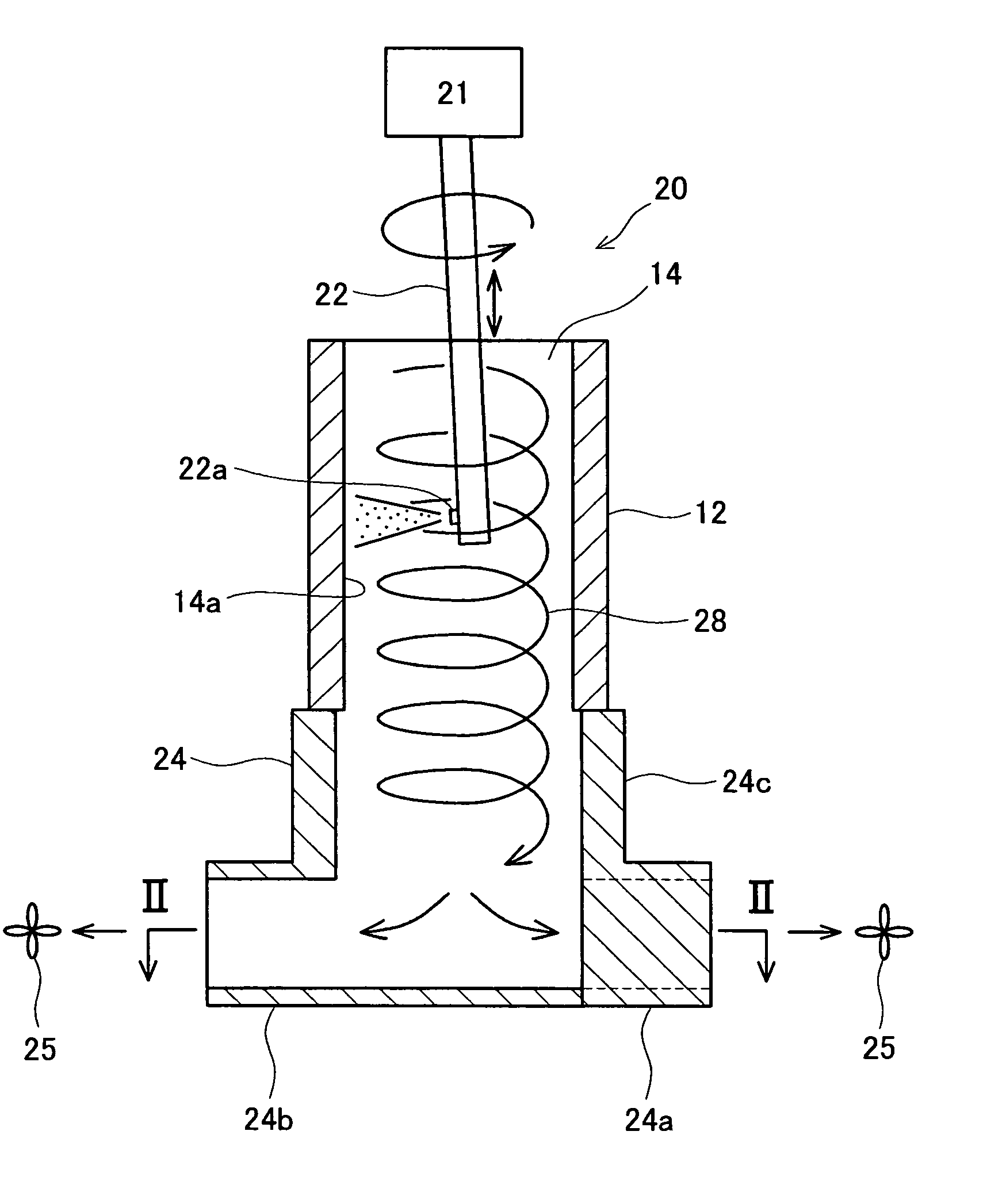
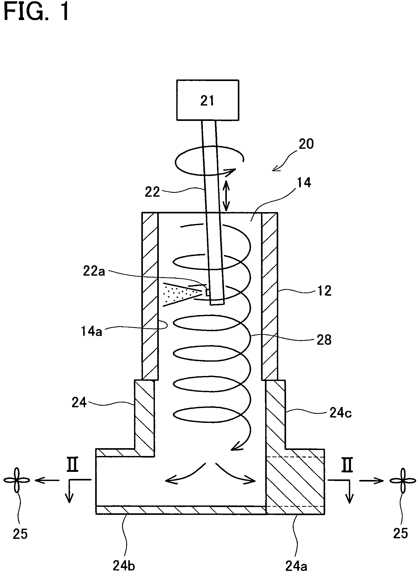
[0029]An embodiment of a thermal spraying device of the present invention and a thermal spraying method are described below with reference to figures.

[0030]As shown in FIG. 1, a thermal spraying device 20 is formed from a thermal spraying gun 22, a raising-lowering device 21 for the thermal spraying gun 22, a suction adaptor 24, and suction fans 25, etc. The thermal spraying gun 22 is inserted into a bore 14 passing through a cylinder block 12 from an upper opening of the bore 14. While being supported by the raising-lowering device 21, the thermal spraying gun 22 rotates while moving up and down. A thermal spraying hole 22a opens into a side face at a tip of the thermal spraying gun 22. An electrode having a positive pole and a negative pole is provided within the thermal spraying hole 22a. Fine iron powder, argon gas, and electric power are supplied to the thermal spraying gun 22 via the raising-lowering device 21. An axis of the thermal spraying gun 22 is inclined relative to an ...


PUM

PropertyMeasurementUnit
thicknessaaaaaaaaaa
flow velocityaaaaaaaaaa
velocityaaaaaaaaaa

Abstract

A method for thermally spraying a film on an inner face of a bore of a cylinder block. A pair of suction pipes generates a spiraling air current in the bore, creating an air flow toward the center of the bore. A spraying device sprays molten metal partaicles including fumes toward the inner face of the bore. The fumes are captured by the spiraling air current and removed from molten metal particles directing toward the inner face of the bore. Molten metal particles from which the fumes are removed form the thermally sprayed film on the inner face of the bore. High-quality thermally sprayed film scarcely containing fumes can be formed on the inner face of the bore.

Description

BACKGROUND OF THE INVENTION[0001]1. Field of the Invention[0002]The present invention relates to a technique for forming a thermally sprayed film on an inner face of a bore of a cylinder block. In particular, the present invention relates to a technique for preventing the thermally sprayed film from peeling.[0003]2. Description of the Related Art[0004]A technique is known whereby, instead of attaching a cylinder liner to a bore that passes through a cylinder block of an engine, a thermally sprayed film is formed directly on an inner face of the bore. When cylinder liners are not attached, the distance between bores can be reduced, allowing the cylinder block to be miniaturized. Further, because combustion heat generated within the bore is transmitted directly to the bore, not attaching cylinder liners allows the cooling efficiency of the engine to be improved. In order to obtain a highly smoothened face, a honing process is performed on the thermally sprayed film formed on the inner...

Claims


Application Information

Patent Timeline
Patent Type & Authority Patents(United States)
IPC IPC(8): C23C4/08C23C4/12F02F1/00B05B13/04B05B13/06B05D7/22C23C4/16
CPCC23C4/16C23C4/127C23C4/134
Inventor MIYAMOTO, NORITAKAITAKURA, EIJI
Owner TOYOTA JIDOSHA KK
Why Eureka
Try Eureka