Spirometer system and method for determining lung functional residual capacity (FRC) with a non-occluding shutter

a functional residual capacity and spirometer technology, applied in the field of spirometer, can solve the problems of difficult to measure lung volume, difficult to handle gases, difficult to use dilution techniques, etc., and achieve the effect of overcompensating background deficiencies

Inactive Publication Date: 2016-07-14
TEL HASHOMER MEDICAL RES INFRASTRUCTURE & SERVICES +2
View PDF6 Cites 4 Cited by
  • Summary
  • Abstract
  • Description
  • Claims
  • Application Information

AI Technical Summary

Benefits of technology

The present invention is a device, system, and method that uses a spirometer with a non-occluding leaf shutter. This shutter deflects air in the flow tube so that it doesn't block the airflow and allows patients to breathe normally during use. This invention solves the problem of previous spirometers that could cause breathing difficulties for patients.

Problems solved by technology

The technical problem addressed in this patent is the difficulty of accurately measuring lung volume, which is important in pulmonary physiology and diagnosis. Existing techniques such as gas dilution and plethysmography have limitations including the use of expensive and difficult to handle gases, large and expensive devices, and difficulty in measuring under stress conditions. The patent describes a new device that offers an alternative to the body box method and is more compact and portable.

Method used


Image

  • Spirometer system and method for determining lung functional residual capacity (FRC) with a non-occluding shutter
  • Spirometer system and method for determining lung functional residual capacity (FRC) with a non-occluding shutter
  • Spirometer system and method for determining lung functional residual capacity (FRC) with a non-occluding shutter

Examples


Embodiment Construction

[0037]The principles and operation of the present invention may be better understood with reference to the drawings and the accompanying description.

[0038]The following figure reference labels are used throughout the description to refer to similarly functioning components are used throughout the specification hereinbelow.

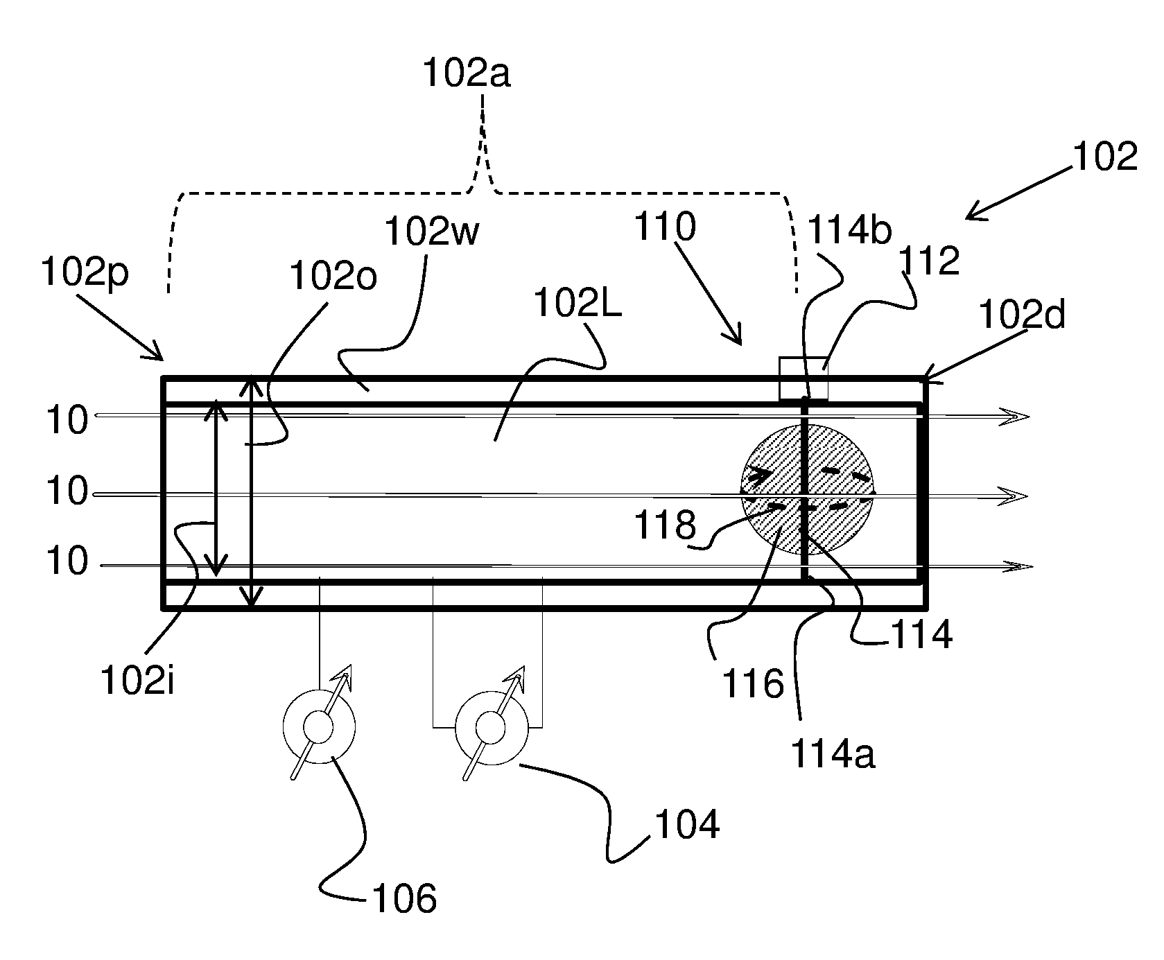
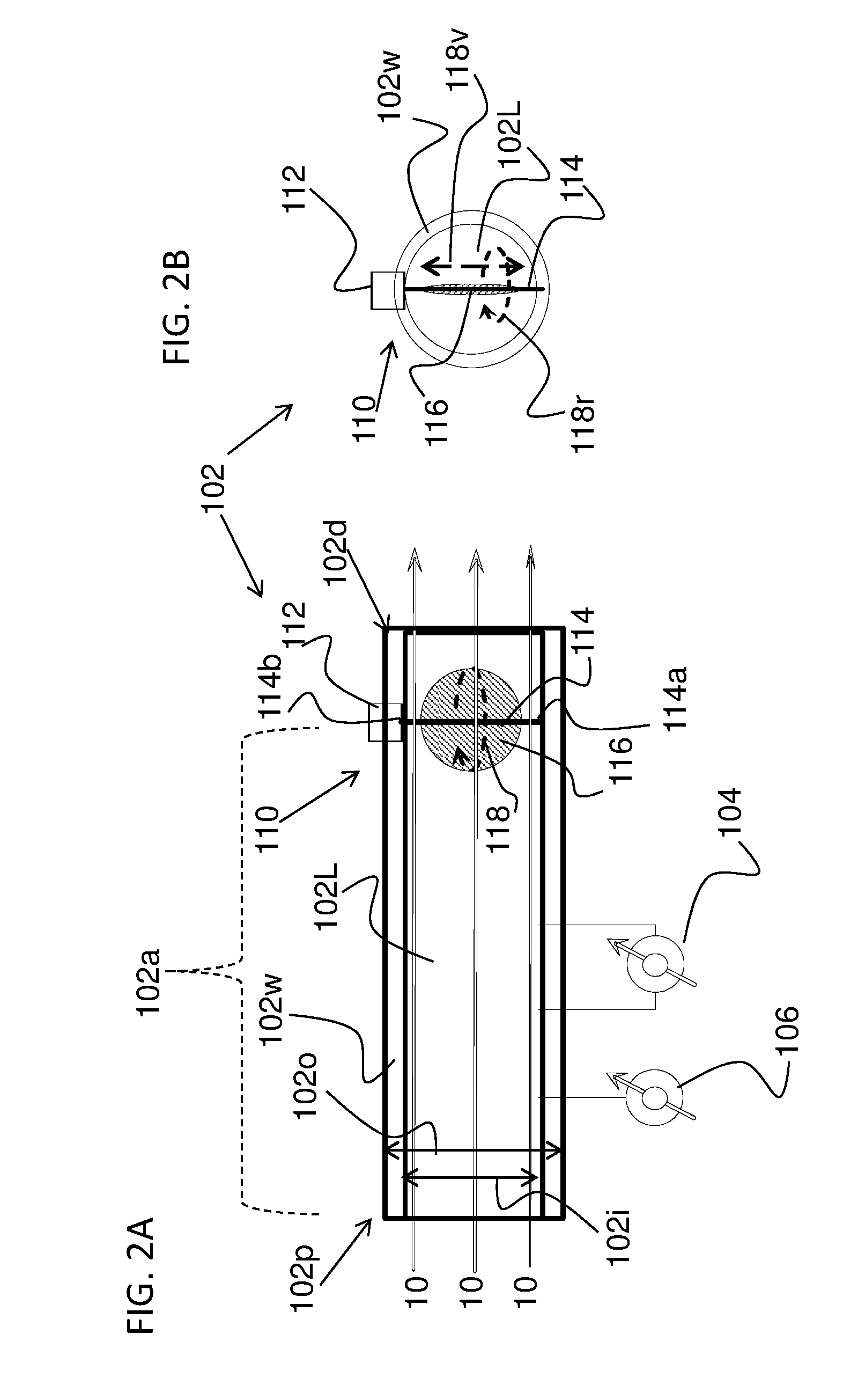
[0039]10 Open air flow

[0040]12 deflected air flow;

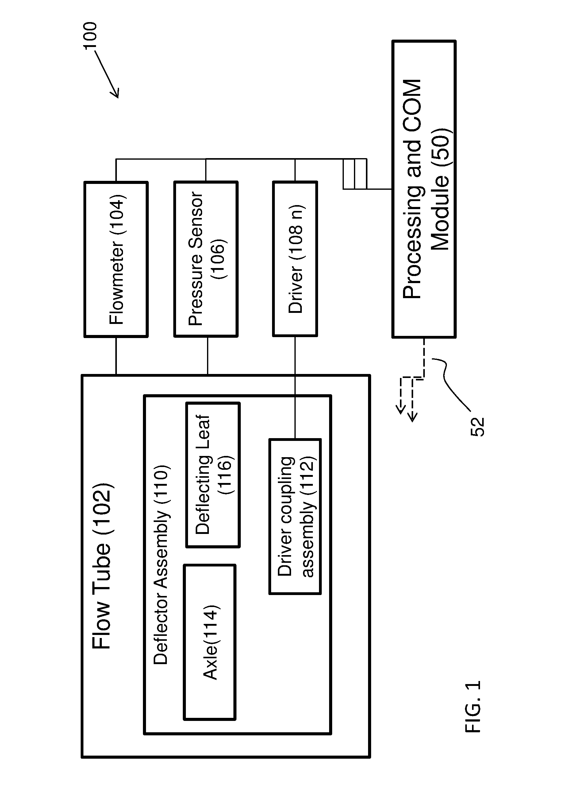
[0041]50 Data processing and communication module;

[0042]52 communication channels;

[0043]100 Flow Tube system

[0044]102 Flow Tube;

[0045]102d Flow Tube distal end;

[0046]102p Flow Tube proximal end;

[0047]102L flow tube lumen;

[0048]102w flow tube wall;

[0049]104 Flow meter;

[0050]106 Pressure Sensor;

[0051]108 driver;

[0052]110 Flow Deflector Apparatus

[0053]112 axle adaptor / coupling assembly;

[0054]114 Axle;

[0055]114a axle first end;

[0056]114b axle second end;

[0057]114d axle distance;

[0058]116 deflector leaf / shutter;

[0059]116d Leaf diameter;

[0060]118r deflector rotational (x-y) axis;

[0061]118v deflector vertical (z) axis;

[006...


PUM


Abstract

The present invention relates to a device, system and a method for determining lung volume and parameters, and in particular, to such a spirometer device, system and method in which a non-occluding shutter is utilized allowing for continuous airflow through the flow tube.

Description


Claims


Application Information

Patent Timeline
Owner TEL HASHOMER MEDICAL RES INFRASTRUCTURE & SERVICES
Why Eureka
Try Eureka