Omniview Camera Tower System

a camera and omni-view technology, applied in the field of camera systems, can solve the problems of limited manipulation of the perspective of conventional poles and tripods, and achieve the effect of improving the accuracy of the effect of adjusting the angle of the camera

Inactive Publication Date: 2016-07-14
GRIFFEY JOHN A
View PDF12 Cites 6 Cited by
  • Summary
  • Abstract
  • Description
  • Claims
  • Application Information

AI Technical Summary

Problems solved by technology

However, a conventional pole and tripod are fairly limited in t...

Method used


Image

  • Omniview Camera Tower System
  • Omniview Camera Tower System
  • Omniview Camera Tower System

Examples


Embodiment Construction

[0015]All illustrations of the drawings are for the purpose of describing selected versions of the present invention and are not intended to limit the scope of the present invention.

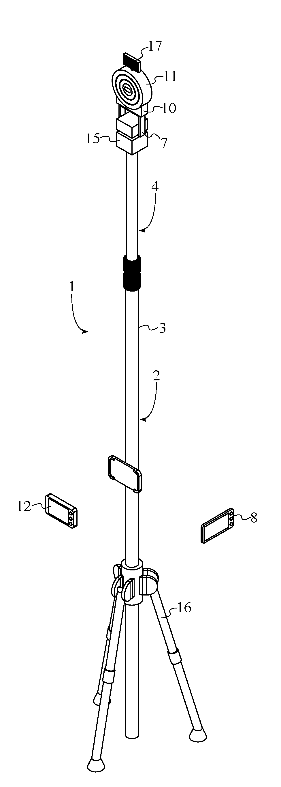
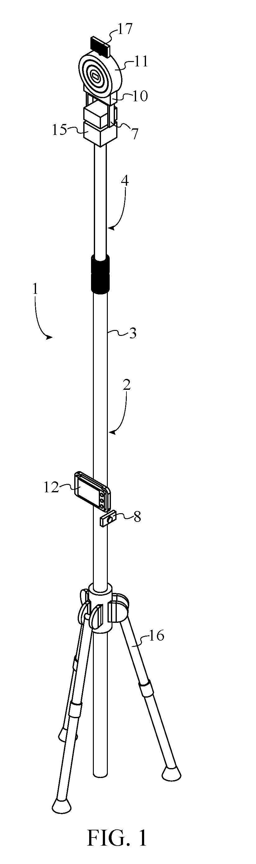
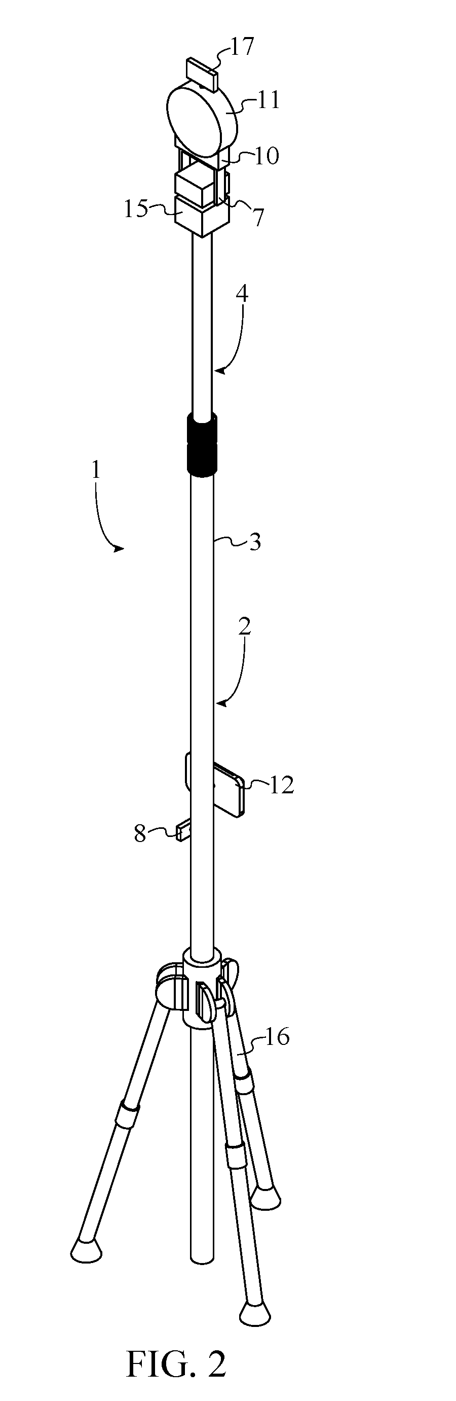
[0016]The present invention is an omniview camera tower system that provides the user with a large degree of leverage over the perspective provided by a camera. The present invention is shown in FIGS. 1-4 and comprises an extendable pole 1, a tilt motor 7, a view adjustment control unit 8, at least one power supply 9, and a camera mount 10. The extendable pole 1 is a two-piece elongated device to which a camera 11 may be mounted in order to position the camera 11 at a distance away from the user while being held or to position the camera 11 in a stationary configuration in a desired location. The extendable pole 1 comprises a base portion 2 and an extension portion 4. The base portion 2 is shown individually in FIG. 5 and is the portion of the extendable pole 1 from which the extension portion 4 is able ...


PUM


Abstract

An omniview camera system allows for the adjustment of the view provided by a camera. The system includes an extendable pole with a base portion as well as an extension portion that may be extended from or retracted into the base portion. A tilt motor is able to tilt an attached camera mount and a camera and a pan motor may be utilized to rotate the camera mount and the camera. The view provided by the camera may be adjusted by manipulating a view adjustment control unit. The view adjustment control unit may be used in a wired or wireless configuration. A live feed of the camera is provided via a removable viewfinder display. The base portion may be secured to a stabilizing base platform in order to ensure that the system remains stable when placed on a surface.

Description

[0001]The current application claims a priority to the U.S. Provisional Patent application Ser. No. 62 / 100,995 filed on Jan. 8, 2015.FIELD OF THE INVENTION[0002]The present invention relates generally to a camera system. More specifically, the present invention is an omniview camera tower system that allows for significant leverage over the perspective provided by a camera.BACKGROUND OF THE INVENTION[0003]One of the most important factors in utilizing a camera to capture images or video is manipulating the placement of the camera in order to achieve the desired perspective of an image or video. This is commonly achieved by utilizing an object such as a pole, tripod, or similar accessory in order to position the camera. A pole allows a camera to be positioned at a higher elevation for an overview of a scene. Similarly, a tripod allows a camera to be fixed in a stationary position in order to capture a scene without being directly held by a photographer or videographer. However, a con...

Claims


Application Information

Patent Timeline
IPC IPC(8): G03B17/56G03B13/10G03B15/03G03B13/02
CPCG03B17/561G03B17/566G03B15/03G03B13/10G03B13/02F16M11/10F16M11/18F16M11/2014F16M11/24F16M11/242H04N23/531H04N23/661H04N23/695
Inventor GRIFFEY, JOHN A.
Owner GRIFFEY JOHN A
Why Eureka
Try Eureka