
Speaker device

a speaker device and speaker technology, applied in the direction of transducer casings/cabinets/supports, electrical transducers, frequency/directions obtaining arrangements, etc., can solve the problem of increasing the cost of the speaker devi

Active Publication Date: 2016-07-14
JAGUAR LAND ROVER LTD
View PDF6 Cites 22 Cited by
  • Summary
  • Abstract
  • Description
  • Claims
  • Application Information

AI Technical Summary

Benefits of technology

The present invention relates to a speaker device, a speaker assembly, and a motor vehicle including a speaker device. The speaker device includes a first diaphragm and a second diaphragm, each with a respective first and second magnet. The magnets are positioned to interact with each other and drive the diaphragms in opposite directions. The speaker device can produce vibrations and acoustic waves by controlling the first and second electrical drive signals. The technical effects of the invention include improved sound quality, reduced size and weight of the speaker device, and improved driving force.

Problems solved by technology

The use of these types of magnets increases the cost of the speaker devices.

Method used


Image

  • Speaker device
  • Speaker device
  • Speaker device

Examples


first embodiment

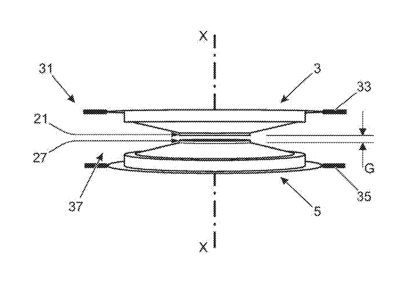
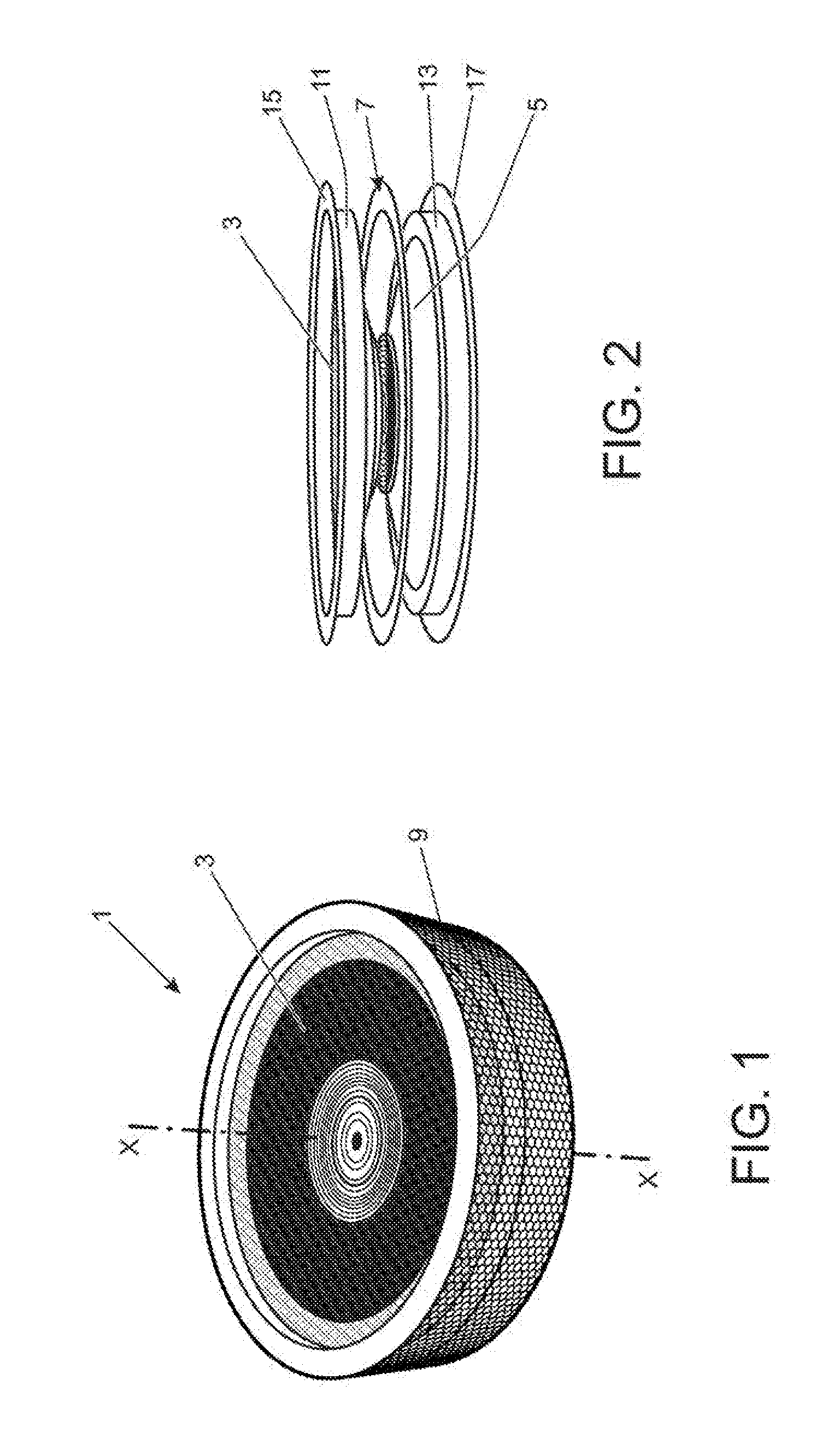
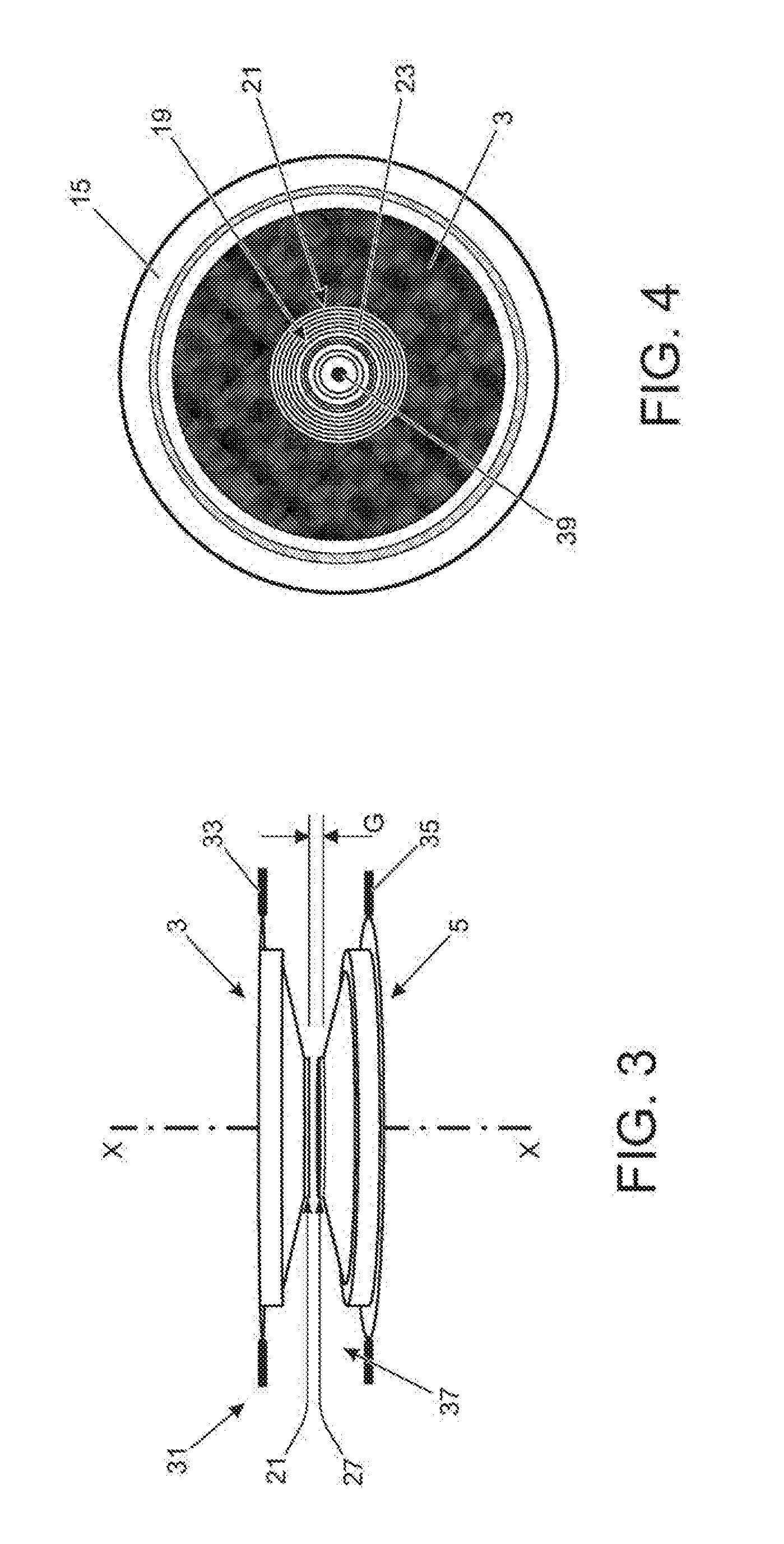
[0027]A speaker device 1 in accordance with the present invention will now be described with reference to FIGS. 1 to 6. The speaker device 1 provides a directional output and has particular application in relation to motor vehicles.

As shown in FIGS. 1 and 2, the speaker device 1 comprises a first diaphragm 3, a second diaphragm 5, a support frame 7 and a silencer 9. The first and second diaphragms 3, 5 are each formed from a resilient membrane having a generally frustoconical configuration which forms a sound producing surface. The first and second diaphragms 3, 5 are fixedly mounted within said support frame 7 and arranged coaxially along a central axis X. As shown in FIGS. 2 and 3, the first and second diaphragms 3, 5 are oriented to face in opposite directions, each diaphragm 3, 5 tapering outwardly along said central axis X. The diameter of the first and second diaphragms 3, 5 can be in the range of 10 cm (4″) to 60 cm (24″).

The support frame 7 comprises first and second annular...

second embodiment

A speaker device 101 according to the present invention is illustrated in FIG. 7. Like reference numerals are used for like components, albeit incremented by 100 for clarity.

The speaker device 101 comprises a first diaphragm 103 mounted to a front face 133 of an enclosure 131. The first diaphragm 103 is generally unchanged from the first embodiment and comprises a membrane having a frustoconical configuration. A first electromagnet 119 is fixedly mounted to a first central region 121 of the first diaphragm 103. The first electromagnet 119 comprises a first coil 123 which forms a first voice coil of the speaker device 101.

The second diaphragm 5 is omitted from this embodiment. Rather, a second electromagnet 125 is fixedly mounted to a back face 135 of the enclosure 131. The second electromagnet 125 comprises a second coil 129 which forms a second voice coil of the speaker device 101. The first and second electromagnets 119, 125 are mounted along the central axis X which is arranged c...


PUM


Abstract

The present invention relates to a speaker device (1) having a first diaphragm (3) and a second diaphragm (5). A first magnet (19) is mounted to the first diaphragm (3) and a second magnet (25) is mounted to the second diaphragm (5). The first magnet (19) is a first electromagnet having a first coil (23) and a power source driver is provided for supplying an electrical drive signal to the first coil (23) to establish said first magnetic field. The first and second magnets (19, 25) are arranged to generate first and second interacting magnetic fields which drive the first and second diaphragms (3, 5). The invention also relates to a speaker device (101) in which the second diaphragm (5) is replaced with a fixed back plate (135). The present invention also relates to a speaker assembly (45) made up of an array of the speaker devices (1; 101). The speaker device (1) can be used in a motor vehicle.

Description

TECHNICAL FIELD[0001]The present invention relates to a speaker device, to a speaker assembly, to a silencer, and to a motor vehicle including a speaker device.BACKGROUND OF THE INVENTION[0002]A conventional loud speaker typically comprises a fixed permanent magnet which interacts with an electromagnet (voice coil) mounted to a diaphragm. By controlling the current supplied to the electromagnet, the diaphragm is driven and the resulting vibrations output acoustic waves. In order to reduce the size and packaging requirements, stronger magnets are required in the loud speakers and these may comprise rare-earth elements, for example neodymium magnets and samarium-cobalt magnets. The use of these types of magnets increases the cost of the speaker devices.It is known from US 2010 / 0080406 to provide a push-pull type speaker device comprising first and second diaphragms. A pair of electromagnets, corresponding to the first and second diaphragms, is provided for cooperating with a permanent...

Claims


Application Information

Patent Timeline
Patent Type & Authority Applications(United States)
IPC IPC(8): H04R9/02H04R1/28H04R1/32H04R9/06
CPCH04R9/025H04R9/063H04R2499/13H04R1/323H04R1/2896H04R7/26H04R9/04H04R9/02H04R9/06H04R11/02H04R1/02H04R1/2803
Inventor TOMAR, ASHUTOSH
Owner JAGUAR LAND ROVER LTD
Learn More