Surgical instruments with force applier and methods of use

a technology of surgical instruments and applicators, applied in the field of surgical instruments, can solve problems such as the inability to achieve traditional sealing methods

Active Publication Date: 2016-07-21
TYCO HEALTHCARE GRP LP
View PDF4 Cites 97 Cited by
  • Summary
  • Abstract
  • Description
  • Claims
  • Application Information

AI Technical Summary

Benefits of technology

[0013]In disclosed embodiments, the method further comprises perfusing blood from the tissue held between the jaw members by retracting the force applier from the cavity of the jaw member, and advancing and retracting the force applier a subsequent number of times through the cavity of the jaw member. It is further disclosed that the method includes detecting a pulse from the tissue held between the jaw members using at least one sensor disposed on the first jaw

Problems solved by technology

In certain types of surgical procedures, e.g., lobectomies, segmentectomies, nephrectomies, etc., when a surgeon wishes to seal thick tissue, such as

Method used


Image

  • Surgical instruments with force applier and methods of use
  • Surgical instruments with force applier and methods of use
  • Surgical instruments with force applier and methods of use

Examples


first embodiment

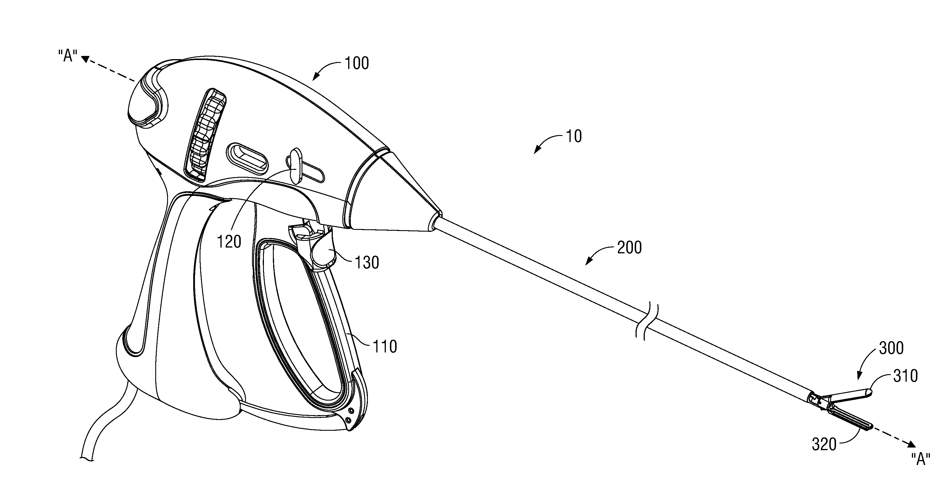
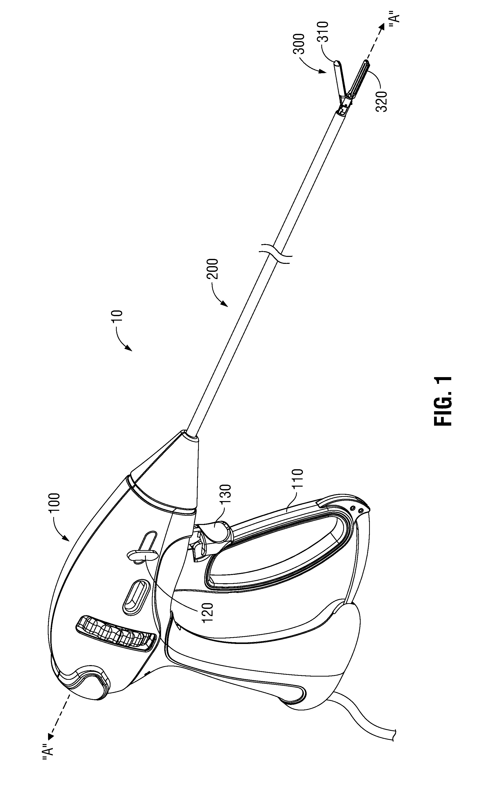
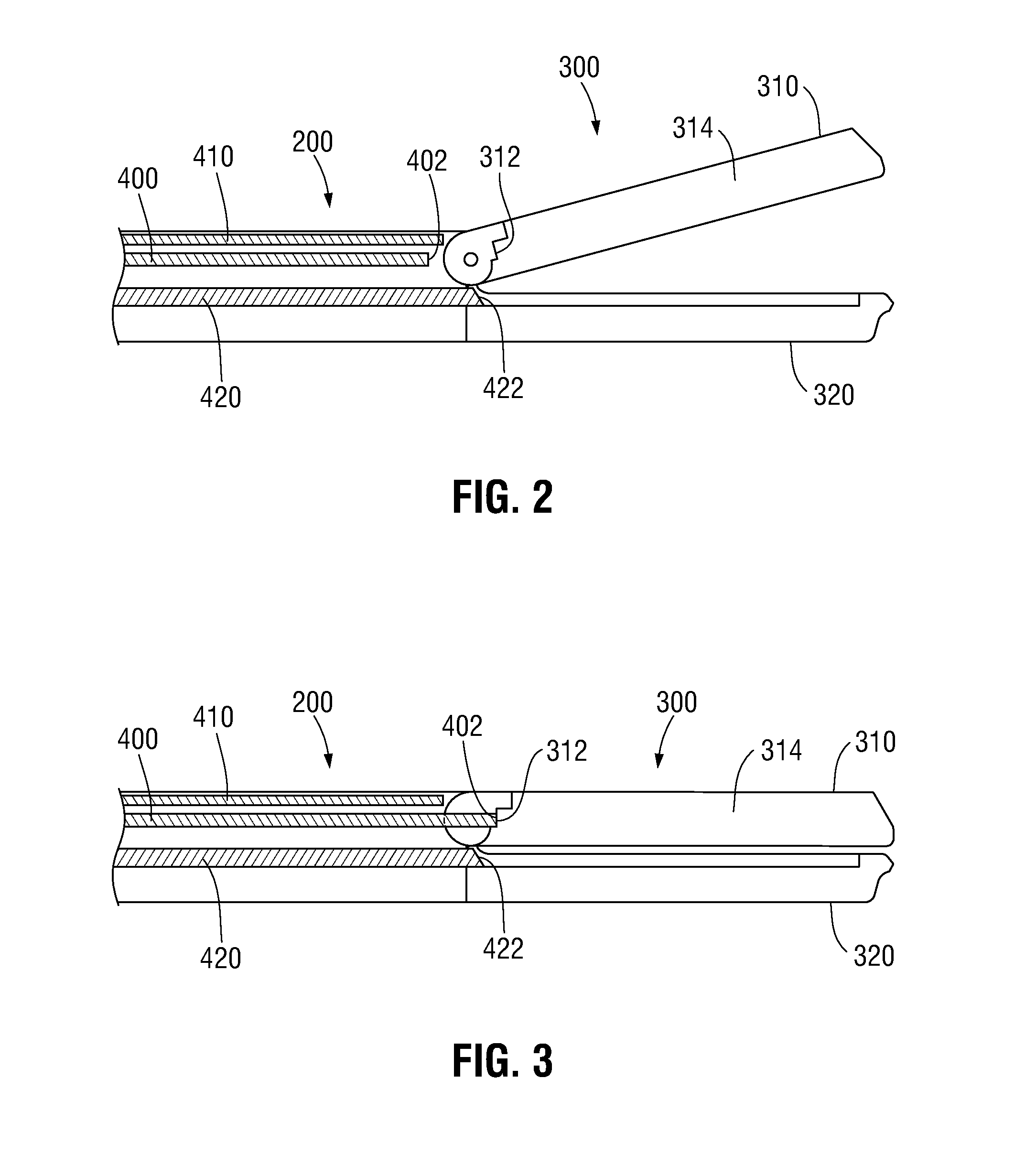
[0037]With reference to FIGS. 6A-6C, various embodiments of jaw members 310 and 320 are shown. FIG. 6A illustrates first jaw member 310 including cavity 314, a seal plate 316, and force applier 410a within cavity 314. Here, force applier 410a includes a “T” cross-section having a horizontal beam 412a and a vertical beam 414a. Second jaw member 320 includes a seal plate 322 for bipolar sealing, and an I-beam 324, e.g., for providing additional strength to the second jaw member 320.

second embodiment

[0038]FIG. 6B illustrates first jaw member 310 including cavity 314, seal plate 316, and force applier 410b within cavity 314. Here, force applier 410b includes a linear cross-section having a horizontal beam 412b. Second jaw member 320 lacks a seal plate, and includes I-beam 324, e.g., for additional strength. Thus, surgical instrument 10 is configured for monopolar sealing.

third embodiment

[0039]FIG. 6C illustrates first jaw member 310 including cavity 314, seal plate 316, and force applier 410c within cavity 314. Here, force applier 410c includes an “I”-shaped cross-section having a first horizontal beam 412c, a vertical beam 414c, and a second horizontal beam 416c. Second jaw member 320 lacks a seal plate, and includes I-beam 324, e.g., for additional strength. Thus, surgical instrument 10 is configured for monopolar sealing.

[0040]The present disclosure also includes combinations of the embodiments of FIGS. 6A-6C and variations of those embodiments, including variations in width, height, length, thickness and / or shape of the various components described and illustrated herein. Additionally, force applier 410 may be made of any suitable material, e.g., steel, for providing the desired strength.

[0041]Moreover, the end effector assembly 300 may include a bilateral jaw member arrangement wherein both jaw members 310, 320 are moveable by first actuator or handle 110. Sec...


PUM


Abstract

A surgical instrument including a housing, an elongated portion, an end effector, a drive beam and a force applier is provided. The housing includes a first actuator and a second actuator. The elongated portion extends distally from the housing and defines a longitudinal axis. The end effector is disposed adjacent a distal portion of the elongated portion, and includes a first jaw member and a second jaw member. The first jaw member has a cavity defined therein. Actuation of the first actuator causes distal translation of the drive beam to move the first jaw member relative to the second jaw member toward the approximated position, which applies a fist force against tissue disposed between the jaw members. Actuation of the second actuator causes distal translation of the force applier such that at least a portion of the force applier moves into the cavity of the first jaw member and applies an additional force against tissue disposed between the jaw members.

Description

CROSS REFERENCE TO RELATED APPLICATION[0001]The present application claims the benefit of and priority to U.S. Provisional Application Ser. No. 62 / 105,961, filed on Jan. 21, 2015, the entire contents of which are incorporated herein by reference.BACKGROUND[0002]1. Technical Field[0003]The present disclosure relates to surgical instruments and, more particularly, to surgical instruments including a force applier for grasping, treating, sealing, stapling, and / or dividing tissue.[0004]2. Description of Related Art[0005]Many surgical instruments are known for sealing, stapling, or otherwise joining tissue. Some of these surgical include one or more movable handles, levers, actuators, triggers, etc. for actuating and / or manipulating one or more functional components of the surgical instrument. For example, a surgical forceps may include a movable handle that is selectively actuatable relative to a stationary handle for moving at least one jaw member with respect to another jaw member of ...

Claims


Application Information

Patent Timeline
IPC IPC(8): A61B17/29A61B17/295A61B17/068A61B18/14
CPCA61B17/29A61B18/1445A61B2017/2938A61B17/068A61B2018/0063A61B17/295A61B17/07207A61B2017/00022A61B2017/07257A61B2017/2932A61B2017/2933A61B2018/00601A61B2018/00791A61B2018/00875A61B2017/2902A61B34/35A61B5/1072A61B2018/00303A61B2018/00642A61B2018/1455A61B2562/0257
Inventor FRUSHOUR, SCOTT E.M.
Owner TYCO HEALTHCARE GRP LP
Why Eureka
Try Eureka