Rotary table and clamping mechanism

a technology of clamping mechanism and rotary table, which is applied in mechanical equipment, fluid actuated brakes, manufacturing tools, etc., can solve the problems of adversely affecting the machining accuracy of workpieces held on the table, insufficient magnitude, and subject to backlash, and achieves high clamping torqu

Inactive Publication Date: 2016-07-21
FANUC LTD
View PDF9 Cites 3 Cited by
  • Summary
  • Abstract
  • Description
  • Claims
  • Application Information

AI Technical Summary

Benefits of technology

[0013]According to the present invention, there can be provided a rotary table capable of providing a high clamping torque and a clamping mechanism of the rotary table.

Problems solved by technology

Since the worm gear mechanism of this type is constructed so that a worm and a worm wheel mesh with each other, it is subject to backlash, though very small.
Even when the table is stationary, therefore, looseness corresponding to the amount of the backlash is caused, so that an indexed angle of the table may be deviated to adversely affect the machining accuracy of a workpiece held on the table.
In the conventional rotary table, the clamping torque is produced by using a single brake disk, so that its magnitude is insufficient.
Further, there is no existing means for easily increasing the clamping torque in the case where a high clamping torque is required after the rotary table is installed by a user.

Method used


Image

  • Rotary table and clamping mechanism
  • Rotary table and clamping mechanism
  • Rotary table and clamping mechanism

Examples


Embodiment Construction

[0018]One embodiment of the present invention will now be described with reference to the accompanying drawings. In the rotary table according to the present embodiment, a motor for driving a rotating shaft is installed in a casing. However, the rotary table according to the present invention is not limited to the configuration in which the motor is disposed in the casing. For example, it may alternatively be a rotary table in which a motor is disposed outside a casing, as described in Japanese Patent Application Laid-Open No. 2002-18678 mentioned before, or a rotary table which includes no motor as a constituent element and in which a jig plate is supported for rotation, as described in Japanese Patent Application Laid-Open No. 2013-144321 mentioned before.

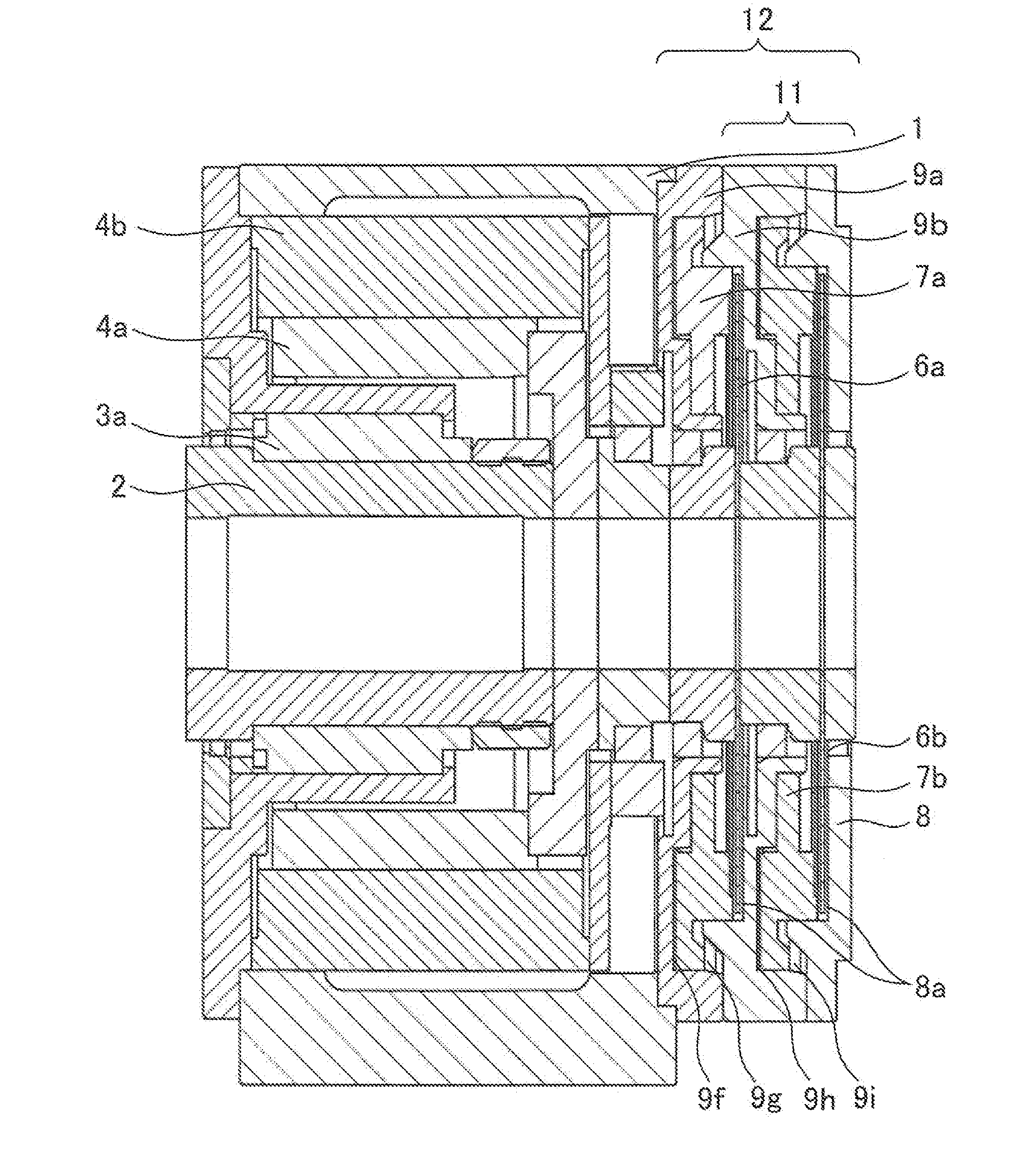
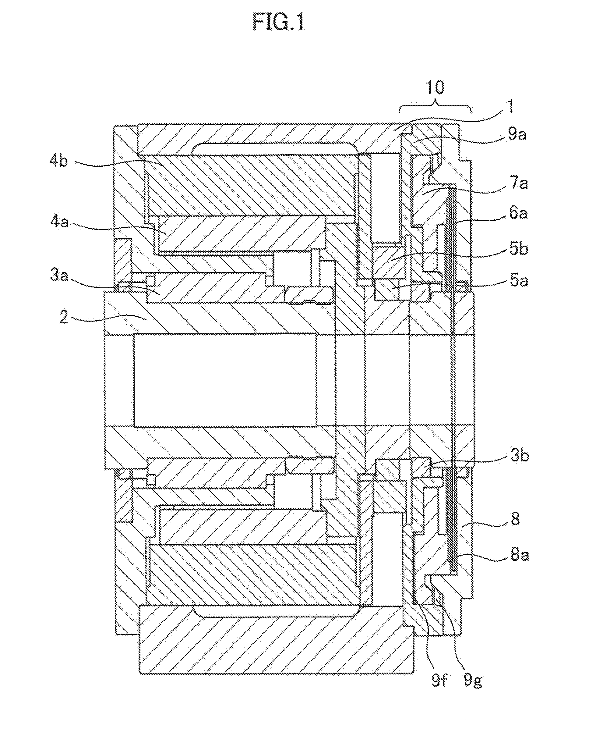
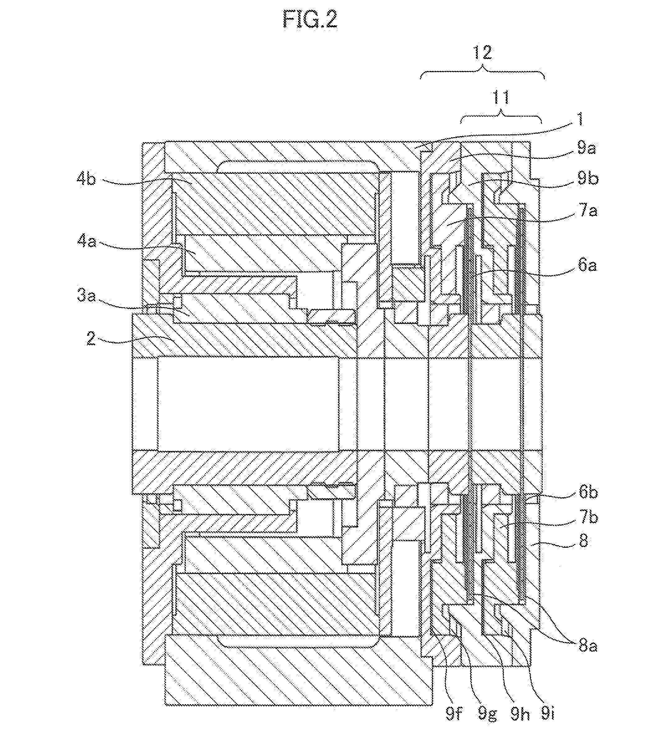
[0019]FIG. 1 is a sectional view showing a basic structure of the rotary table. FIG. 2 is a sectional view of one embodiment of the rotary table according to the present invention.

[0020]As shown in FIG. 1, a shaft 2 of the rotary...


PUM


Abstract

A rotary table, which is provided with a rotating shaft rotatably disposed in a casing and a clamping mechanism configured to disable the rotating shaft from rotating, is designed so that another clamping mechanism, in addition to the first clamping mechanism, can be connected to the rotating shaft, whereby a clamping torque twice that of a rotary table with a single clamping mechanism can be produced.

Description

BACKGROUND OF THE INVENTION[0001]1. Field of the Invention[0002]The present invention relates to a rotary table and a clamping mechanism used in a machine tool.[0003]2. Description of the Related Art[0004]In recent years, rotary tables have become widely used in machine tools. In particular, the rotary tables are frequently used to perform indexing operations, and the reliability of the indexing operations and clamping mechanisms is an important element of the rotary tables.[0005]In general, an irreversible worm gear mechanism is used as a rotating mechanism of a rotary table (see, for example, Japanese Patent Application Laid-Open No. 2002-18678). Since the worm gear mechanism of this type is constructed so that a worm and a worm wheel mesh with each other, it is subject to backlash, though very small. Even when the table is stationary, therefore, looseness corresponding to the amount of the backlash is caused, so that an indexed angle of the table may be deviated to adversely affe...

Claims


Application Information

Patent Timeline
Patent Type & Authority Applications(United States)
IPC IPC(8): B23Q16/10F16D55/24F16D55/02
CPCB23Q16/105F16D55/02F16D55/24F16D55/025B23Q1/26B23Q2220/004F16D55/32
Inventor XIA, ZHIZHEN
Owner FANUC LTD
Why Eureka
Try Eureka