

Improved terminal, particularly for automatic circuit breakers
A technology of terminals and terminal blocks, which is applied in the direction of protective switch terminals/connections, circuits, and contact parts manufacturing, which can solve the problems of low clamping torque value and increased production cost.
- Summary
- Abstract
- Description
- Claims
- Application Information
AI Technical Summary
Problems solved by technology
Method used
Image

Examples
Embodiment Construction
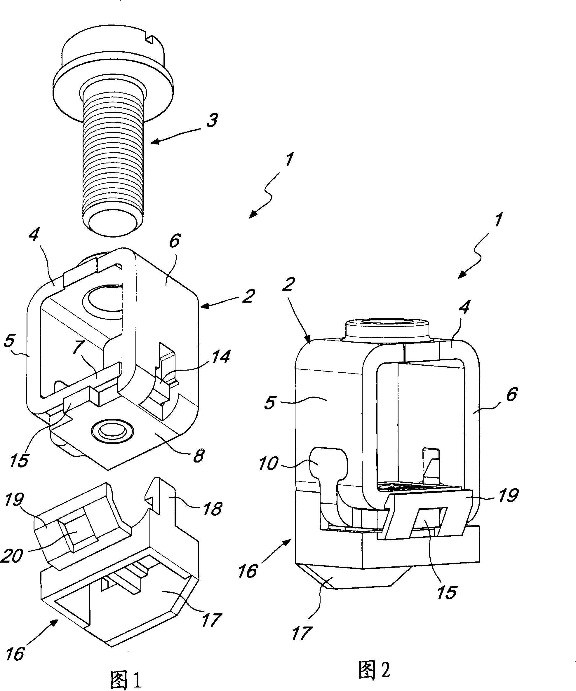
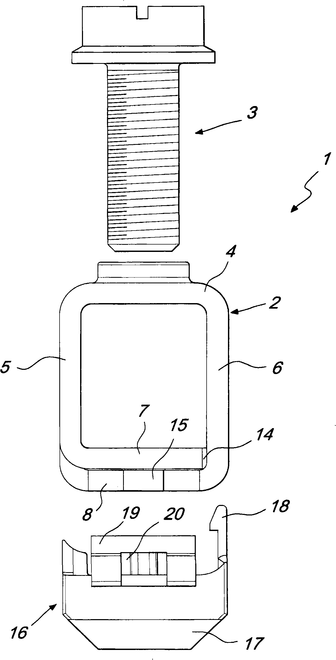
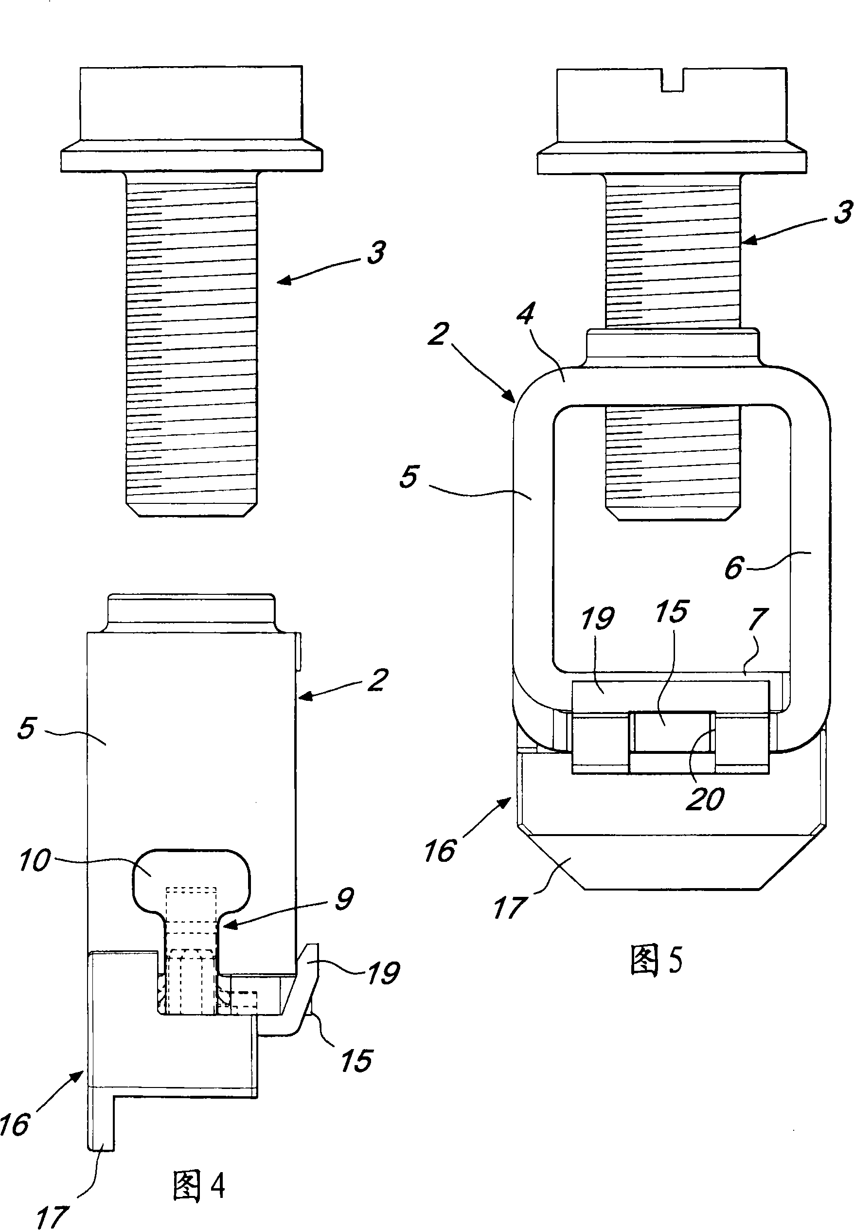
[0031] Referring to the above-mentioned figures, the terminal according to the invention is generally designated by the numeral 1 and comprises a parallelepiped-shaped body 2 and a clamping screw 3 . The pressing screw 3 is connected with the body 2, so that the end of the conductive cable (not shown in the figure) can be pressed against by acting on the screw, so that the end of the cable is located in the body 2 inside the parallelepiped 2 between the bottom of the connector and the end of the terminal strip (not visible in the figure).
[0032] The parallelepiped 2 is formed from a single metal sheet which has been punched and bent.
[0033] The body 2 is composed of an upper surface 4 and two side walls integrated with the upper surface, the two side walls are respectively a first side wall 5 and a second side wall 6 .
[0034] The end of the first side wall 5 has an inner underside 7 and the end of the second side wall 6 has an outer underside 8 .
[0035] The two under...
PUM
 Abstract
Description
Claims
Application Information