Eureka AIR delivers breakthrough ideas for toughest innovation challenges, trusted by R&D personnel around the world.

Laminate composite wing structures

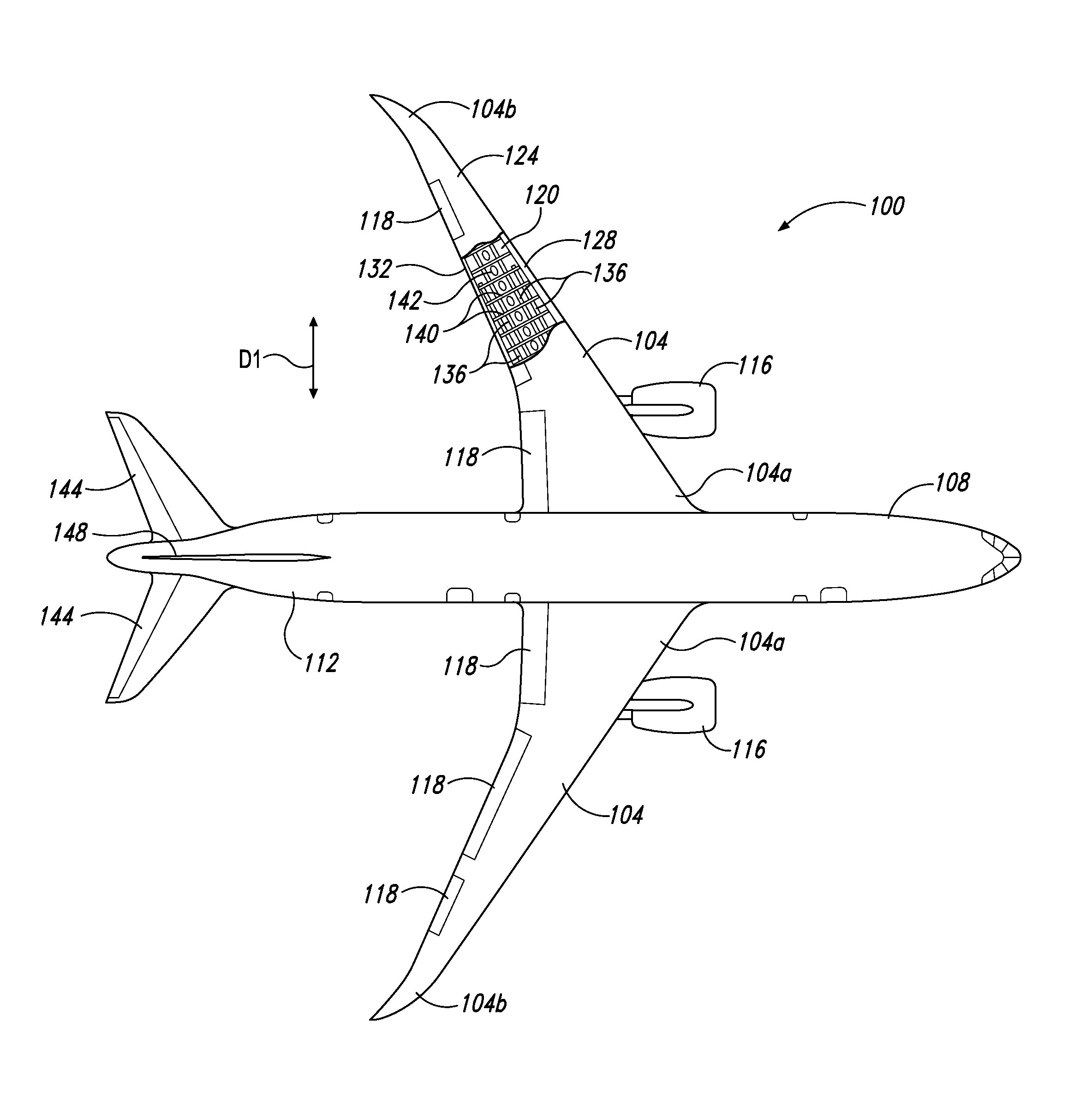
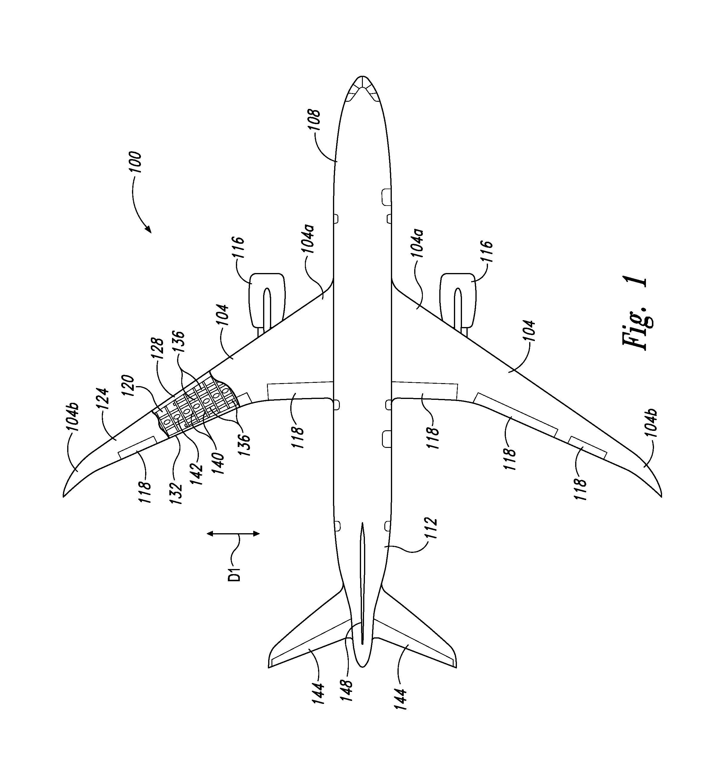
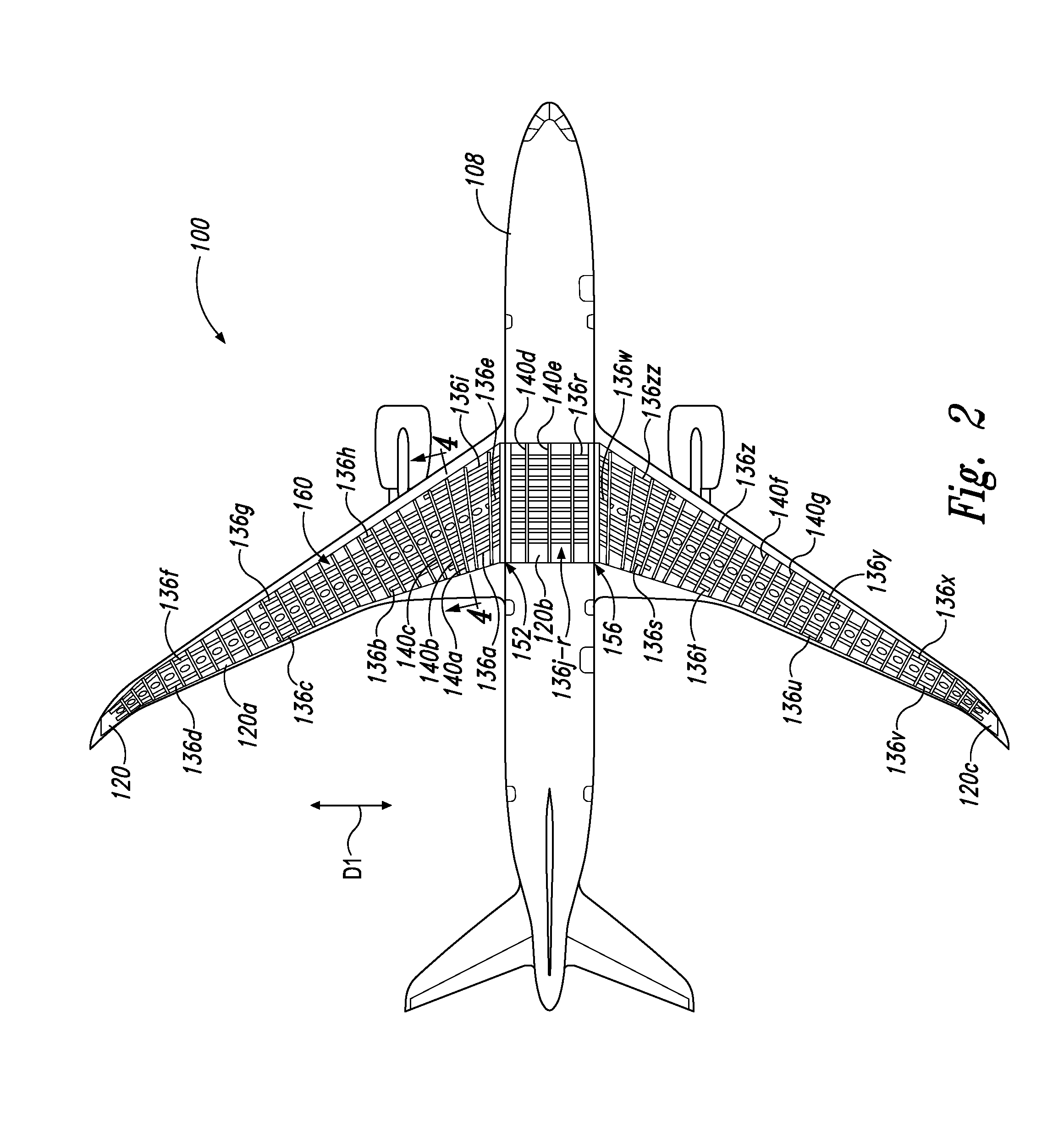
a composite wing and laminate technology, applied in sandwich constructions, transportation and packaging, spars/stringers, etc., can solve the problems of increased exterior vertical profile, reduced internal clearance, and difficulty in constructing i-shaped stringers or t-shaped stringers that are curved, and achieve the effect of stiffening the wing

Active Publication Date: 2016-07-21
THE BOEING CO
View PDF11 Cites 24 Cited by
  • Summary
  • Abstract
  • Description
  • Claims
  • Application Information

AI Technical Summary

Benefits of technology

The patent describes a method for stiffening the wing of an aircraft by adding a rib to the inner surface of the lower wing skin and a stringer made of reinforcement material to the interior surface of the wing. The rib is positioned perpendicular to the length of the wing. The method also involves using a fastener to join the rib to the lower wing skin and the stringer, which stiffens the wing. The technical effect of this method is that it provides structural strength and stiffness to the wing, which improves the performance of the aircraft.

Problems solved by technology

This complicated rib-to-panel interface is typically required as ribs generally cannot be attached to the respective upper (free) flanges of the carbon fiber stiffeners, as the carbon fiber stiffeners are characterized by several individual charges which are bonded together and have a tendency to separate under rib-induced loads.
Further, the upper flanges typically extend significantly from the lower wing skin into the interior of the wing box, resulting in decreased internal clearance (e.g., for performing maintenance) and an increased exterior vertical profile, which may be undesirable in some applications.
Further, it is generally difficult to construct ‘I’ shaped stringers or ‘T’ shaped stringers that are curved.
Moreover, structural characteristics of such bladed curved stringers may result in these stringers being more susceptible to rollover loads.

Method used


Image

  • Laminate composite wing structures
  • Laminate composite wing structures
  • Laminate composite wing structures

Examples


example 2

[0087]This example describes an illustrative one-piece wing embodiment, which may be alternatively included in aircraft 100; see FIGS. 8-11.

[0088]In this example, wing skin 120 may be continuous (or substantially continuous) between wing tips 104c, 104d of wing 104, as can be seen in FIGS. 8 and 9. Further, stringers 136 may include a plurality of stringers, such as stringers 800a-i, which may each be similar in structure to stringer 136g described above.

[0089]As can be seen, stringers 800a-i may each be curved and extend continuously from one of wings 104 to an adjacent wing 104 of aircraft 100. For example, stringers 800a-i may have one or more sweeping curvatures (e.g., in an aft-ward direction, as shown in FIGS. 8 and 11), and one or more dihedral curvatures (e.g., in an up-ward direction, as shown in FIGS. 9 and 10). Associated axes of the one or more sweeping curvatures may be substantially orthogonal to associated axes of the one or more dihedral curvatures. Such mutually ort...

example 3

[0095]This example describes a method for stiffening a wing; see FIG. 12. Aspects of components described herein may be utilized in the method steps described below. Where appropriate, reference may be made to previously described components and systems that may be used in carrying out each step. These references are for illustration, and are not intended to limit the possible ways of carrying out any particular step of the method.

[0096]FIG. 12 is a flow chart illustrating steps performed in an illustrative method, and may not recite the complete process. In particular, FIG. 12 depicts multiple steps of a method, generally indicated at 1200, which may be performed in conjunction with disclosed embodiments according to aspects of the present disclosure. Although various steps of method 1200 are described below and depicted in FIG. 12, the steps need not necessarily all be performed, and in some cases may be performed in a different order than the order shown.

[0097]For example, method...

example 4

[0101]This example describes a method of forming (or manufacturing) a tension panel, such as wing skin 120, with respective stringers, such as stringers 136 (e.g., stringers 136a-z, 136zz and / or stringers 800a-k) structurally joined thereto; see FIGS. 13-15.

[0102]As shown in FIG. 13, a plurality of plies of skin reinforcement material, generally indicated at 1300, may be stacked on a skin caul 1304. For example, plies 1304 may correspond to an uncured configuration of plies 502, which when cured may form lower wing skin 120. For example, plies 1304 may correspond to a plurality of generally planar carbon fiber pre-preg plies with various angular orientations. For example, plies 1304 may correspond to plies P1-P36 shown in Table 3 below, with ply P1 corresponding to the ply adjacent caul 1304, ply P36 being furthest from caul 1304, and plies P2-P35 being serially disposed there between.

TABLE 3PlyOrientationP145P290P3−45P40P545P60P7−45P80P945P100P11−45P1290P1345P140P15−45P160P1745P180...


PUM


Abstract

A wing may include a wing skin, a laminate composite first stringer, a rib, and at least one fastener. A majority of the first stringer may be characterized by a stacked plurality of generally planar plies of reinforcement material structurally joined as a stack to an interior surface of the wing skin and extending generally parallel to the interior surface and a span-wise direction of the wing along a substantial portion of the interior surface. The first stringer may have a generally solid trapezoidal cross section when viewed in a plane that is generally perpendicular to the span-wise direction. The rib may be positioned adjacent the interior surface, and may extend generally perpendicular to the span-wise direction. The trapezoidal cross section may be interfaced with the rib flange. The fastener may extend through the wing skin, the trapezoidal cross section, and the rib flange.

Description

FIELD[0001]This disclosure relates to laminate composite wing structures. More specifically, the disclosed embodiments relate to systems and methods for stiffening a wing, such as that of an aircraft wing assembly, that of an aircraft horizontal stabilizer assembly, and / or that of a control surface torque box assembly.INTRODUCTION[0002]It is desirable for aircraft structures to be capable of reacting to loads in a variety of different directions. For example, it is desirable for an aircraft wing to be capable of reacting to aerodynamic loads that are imposed on the wing during flight. Such aerodynamic loads include bending loads that are reacted by a wingbox structure of the wing, or components thereof.[0003]Generally, a wingbox structure of an aircraft includes a stiffened upper panel, a stiffened lower panel, a front spar that connects the leading edges of the panels, a rear spar that connects the trailing edges of the panels, and internal ribs that provide shape and support and c...

Claims


Application Information

Patent Timeline
Patent Type & Authority Applications(United States)
IPC IPC(8): B64C3/18B64C3/26
CPCB64C3/187B64C3/182B64C3/26B64C3/18B64C1/064B64C1/12B64C3/20Y02T50/40
Inventor CHARLES, JORDANSAMPEDRO-THOMPSON, WILLIAM M.WATKINS, JESSICA L.ROACHE, RYAN CHRISTOPHERGAMBLE, MICHAEL JOHNDOWNEY, TYLER W.CHOY, WENDELL C.K.SANTINI, GREGORY M.
Owner THE BOEING CO
Why Eureka
Eureka Blog
Learn More