MEMs Amplitude Modulator and MEMs Magnetic Field Sensor Including Same

a technology of magnetic field sensor and amplitude modulator, which is applied in the direction of amplitude modulation with mechanical/acoustic driven parts, magnetic field measurement using permanent magnets, instruments, etc., can solve the problems of difficult to detect the desired signal, difficult to obtain a sufficient mechanical displacement, etc., to improve the sensing function, the effect of increasing the variation in the variable capacitance of the variable devi

Active Publication Date: 2016-07-21
LG INNOTEK CO LTD
View PDF1 Cites 10 Cited by
  • Summary
  • Abstract
  • Description
  • Claims
  • Application Information

AI Technical Summary

Benefits of technology

[0012]According to the MEMS amplitude modulator of the embodiment, when a carrier signal and a driving signal of a resonance frequency are simultaneously applied, a signal modulated with the carrier signal due to the mechanical resonance is output, so that it is possible to perform an amplitude modulation without configuring a complex circuit.
[0013]In addition, the MEMS device is a single structure does not including any insulating layers and is driven by applying a single signal thereto, so that the driving of the MEMS device is simple. In addition, all the driving electrodes on both ends of the MEMS device are driven so that the amount of variation in the variable capacitance thereof is increased twice, thereby improving the sensing function.
[0014]In addition, when the MEMS device is used as a magnetic field sensor through various signal detection schemes, the output modulated signal may be processed to detect the intensity of a magnetic field.

Problems solved by technology

However, since Lorentz force utilized to sense a magnetic field is very small relative to gravity, there is a limitation on designing a structure of a sensor such as a spring, so that it is difficult to obtain a sufficient mechanical displacement.
In addition, when a signal, which is varied while AC or DC current is applied to the driving electrode for driving, is detected, it is not easy to detect a desired signal due to a mixing of currents

Method used


Image

  • MEMs Amplitude Modulator and MEMs Magnetic Field Sensor Including Same
  • MEMs Amplitude Modulator and MEMs Magnetic Field Sensor Including Same
  • MEMs Amplitude Modulator and MEMs Magnetic Field Sensor Including Same

Examples


Embodiment Construction

[0025]Hereinafter, the exemplary embodiment of the present invention will be described with reference to the accompanying drawings. However, the present invention is not limited to the exemplary embodiment described below, but can be implemented in various forms.

[0026]In the following description, when a predetermined part “includes” a predetermined component, the predetermined part does not exclude other components, but may further include other components unless otherwise indicated.

[0027]The embodiment provides an amplitude modulator to which a microelectromechanical system (MEMS) device having an enlarged mechanical displacement is applied and a magnetic field sensor including the same.

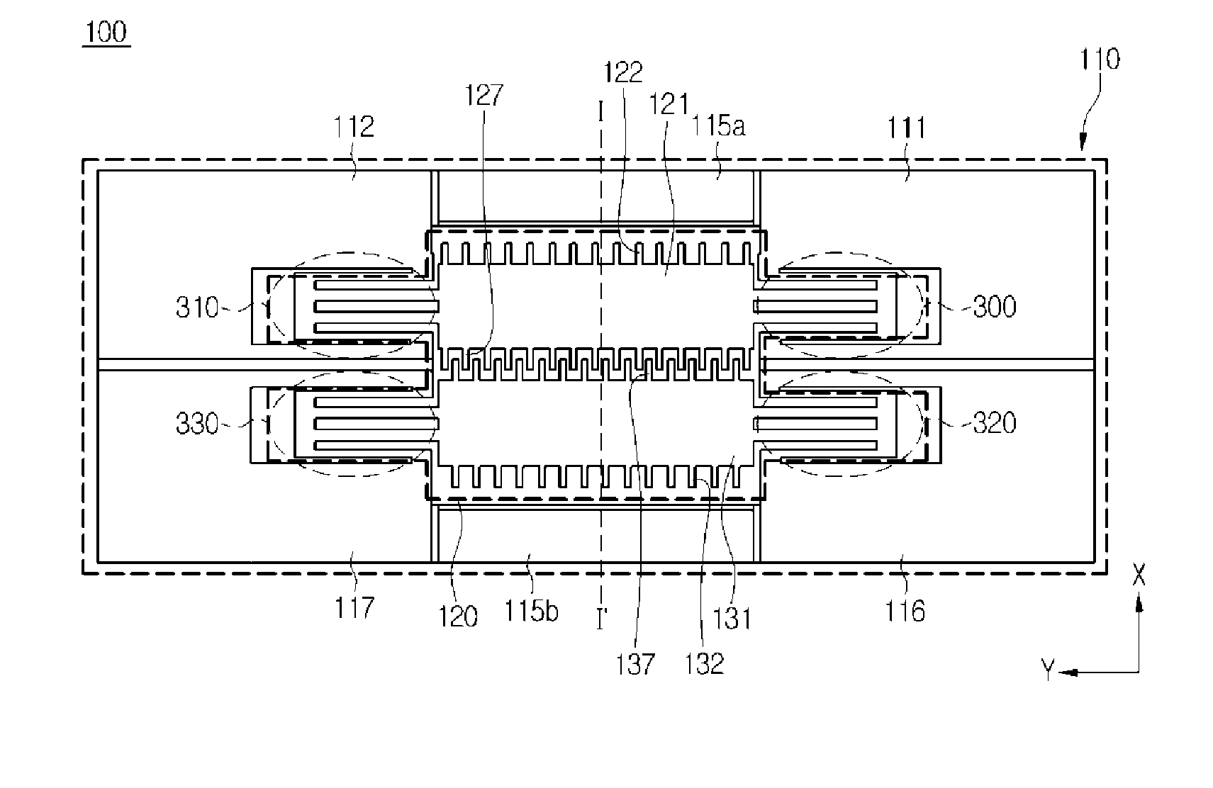
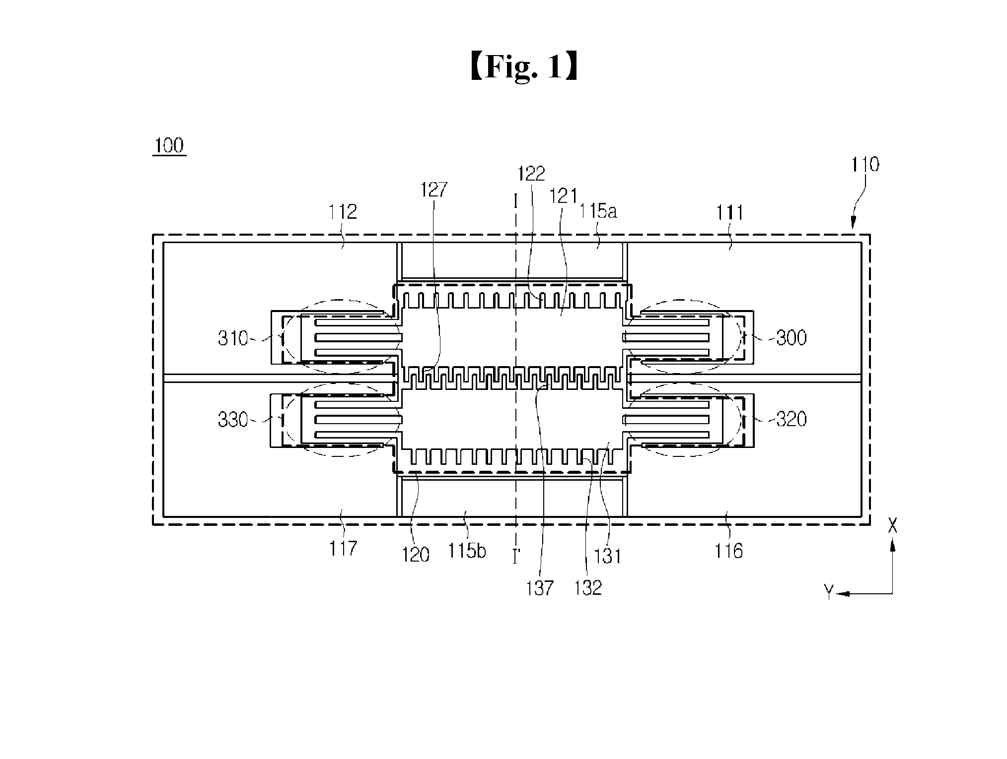
[0028]Hereinafter, an amplitude modulator according to the embodiment will be described with reference to FIGS. 1 to 3.

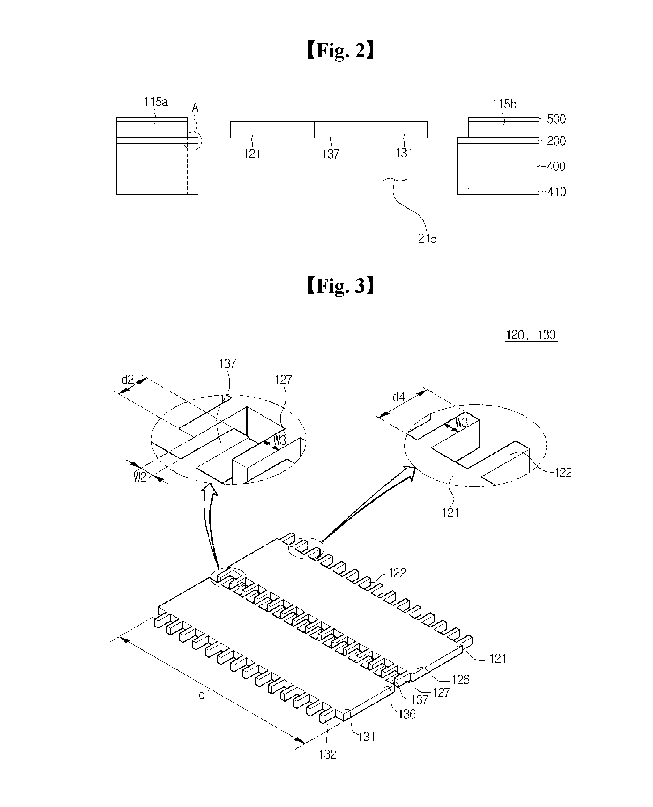
[0029]FIG. 1 is a top view showing an amplitude modulator according to a first embodiment. FIG. 2 is a sectional view taken along line I-I′ of the amplitude modulator shown in FIG....


PUM


Abstract

The present invention provides an amplitude modulator, which is disposed in an area through which a magnetic field flows so as to modulate amplitudes, comprising: a substrate; a first driving electrode which receives a first frequency signal and a second frequency signal supplied from the substrate and carries out resonant motion by the magnetic field; and a second driving electrode for receiving the second frequency signal and carries out resonant motion by the first driving electrode and the magnetic field, wherein a modulated signal is generated by modulating the amplitudes of the first and second frequency signals through the resonant motions of the first and second driving electrodes. Therefore, since the signal generated by modulating a carrier signal through mechanical resonance according to the magnetic field is outputted, amplitude modulation can be carried out without a complicated circuit configuration. In addition, since an MEMS device is a single structure that does not include an insulating layer, a single signal is applied to one structure, thereby simplifying driving, and all the driving electrodes of both ends thereof are driven so as to double a change in variable capacitance, thereby improving sensing ability.

Description

TECHNICAL FIELD[0001]The embodiment relates to a microelectromechanical system (MEMS) amplitude modulator and a MEMS magnetic field sensor including the same.BACKGROUND ART[0002]In general, a magnetic field sensor based on a MEMS capacitive sensing technique includes a driving electrode movable in response to a magnetic field and a fixed electrode able to sense a capacitive variation corresponding to the movement of the driving electrode.[0003]According to the magnetic field sensor principle, when reference current flows into the driving electrode in a predetermined direction, the driving electrode moves in a positive or negative direction to the fixed electrode due to Lorentz force according to the direction and intensity of magnetic field introduced from an outside.[0004]In this case, a distance between both electrodes and an overlapped area of both electrodes are changed so that capacitance is changed. Thus, by detecting the variation in capacitance or a signal varying correspond...

Claims


Application Information

Patent Timeline
Patent Type & Authority Applications(United States)
IPC IPC(8): H03C1/46G01R33/028
CPCG01R33/0286H03C1/46G01R33/038G01R33/00G01R33/02G01R33/0052G01R33/06
Inventor JI, CHIL YOUNGKO, YONG JUNKWON, SEUNG HWASEO, SANG WONKIM, CHULSEO, JEONG GIJUN, DO HANCHOI, WAN SEOP
Owner LG INNOTEK CO LTD
Why Eureka
Try Eureka