

Sliding member and method for producing same
a sliding member and sliding technology, applied in the field of sliding members, can solve the problems of high manufacturing cost of both bearings, and achieve the effect of enhancing the sliding property and durability of the sliding surfa
- Summary
- Abstract
- Description
- Claims
- Application Information
AI Technical Summary
Benefits of technology
Problems solved by technology
Method used
Image

Examples
second embodiment
[0079]Next, description is made of a second embodiment of the present invention.
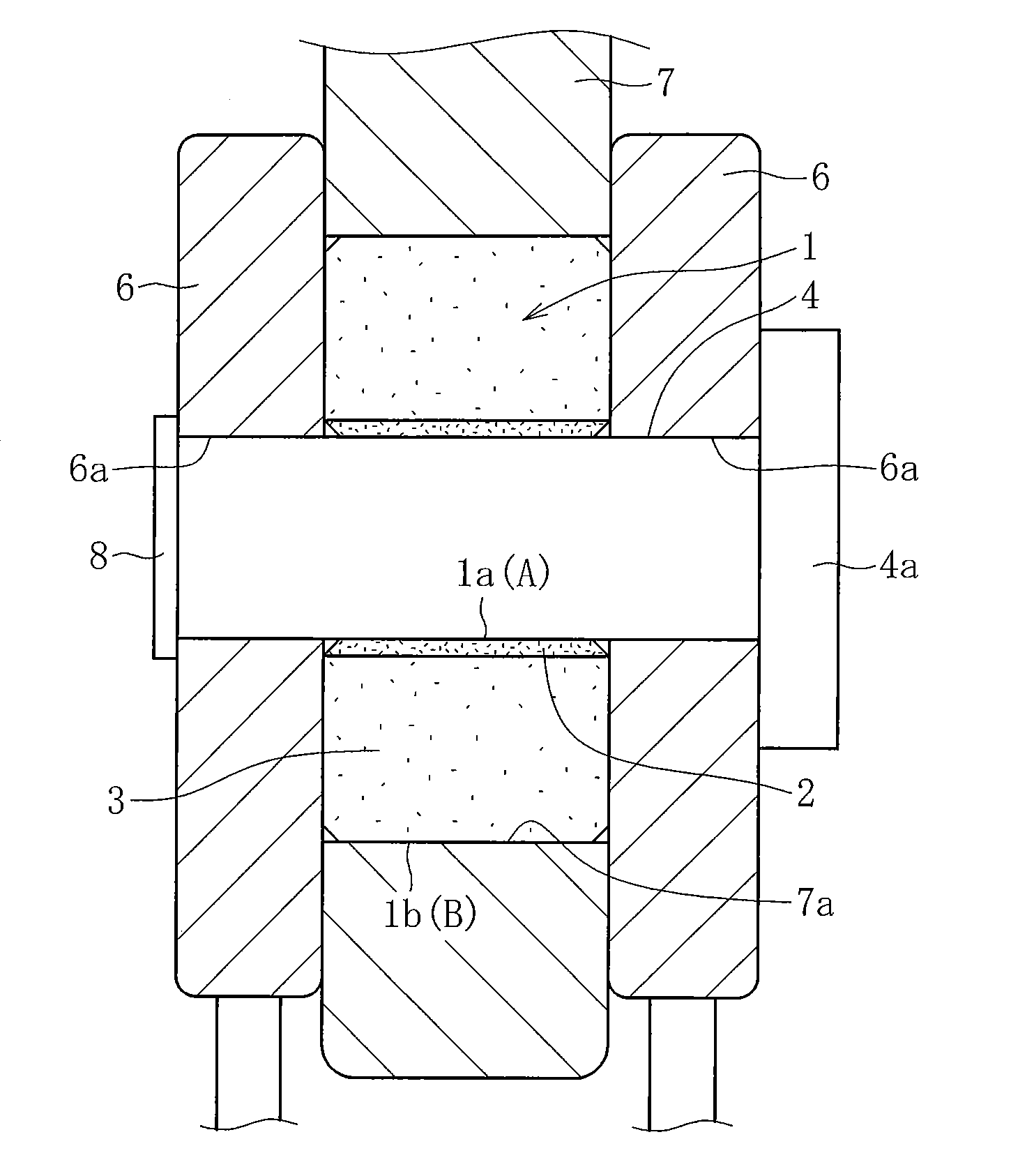
[0080]Similarly to FIG. 1, FIG. 15 is a view for conceptually illustrating a cross-section of a joint portion of an arm of construction machinery. At this joint portion, the first arm 6 is arranged on a distal end side of the arm with respect to the second arm 7. In this case, the pin 4 fixed to the first arm 6 relatively sinks by gravity applied to the first arm 6. The pin 4 to serve as a shaft is supported by a lower region of the inner peripheral surface 1a of the sintered bearing 1. Thus, at the time of the relative rotation between the first arm 6 and the second arm 7, the pin 4 slides relative mainly to the lower region of the inner peripheral surface 1a of the sintered bearing 1.
[0081]In this embodiment, a cross-section of the sliding layer 2 orthogonal to the axial direction (horizontal cross-section) is formed into a partially cylindrical shape with ends (semi-cylindrical shape). Further, a hori...
third embodiment
[0084]Now, description is made of a third embodiment of the present invention.
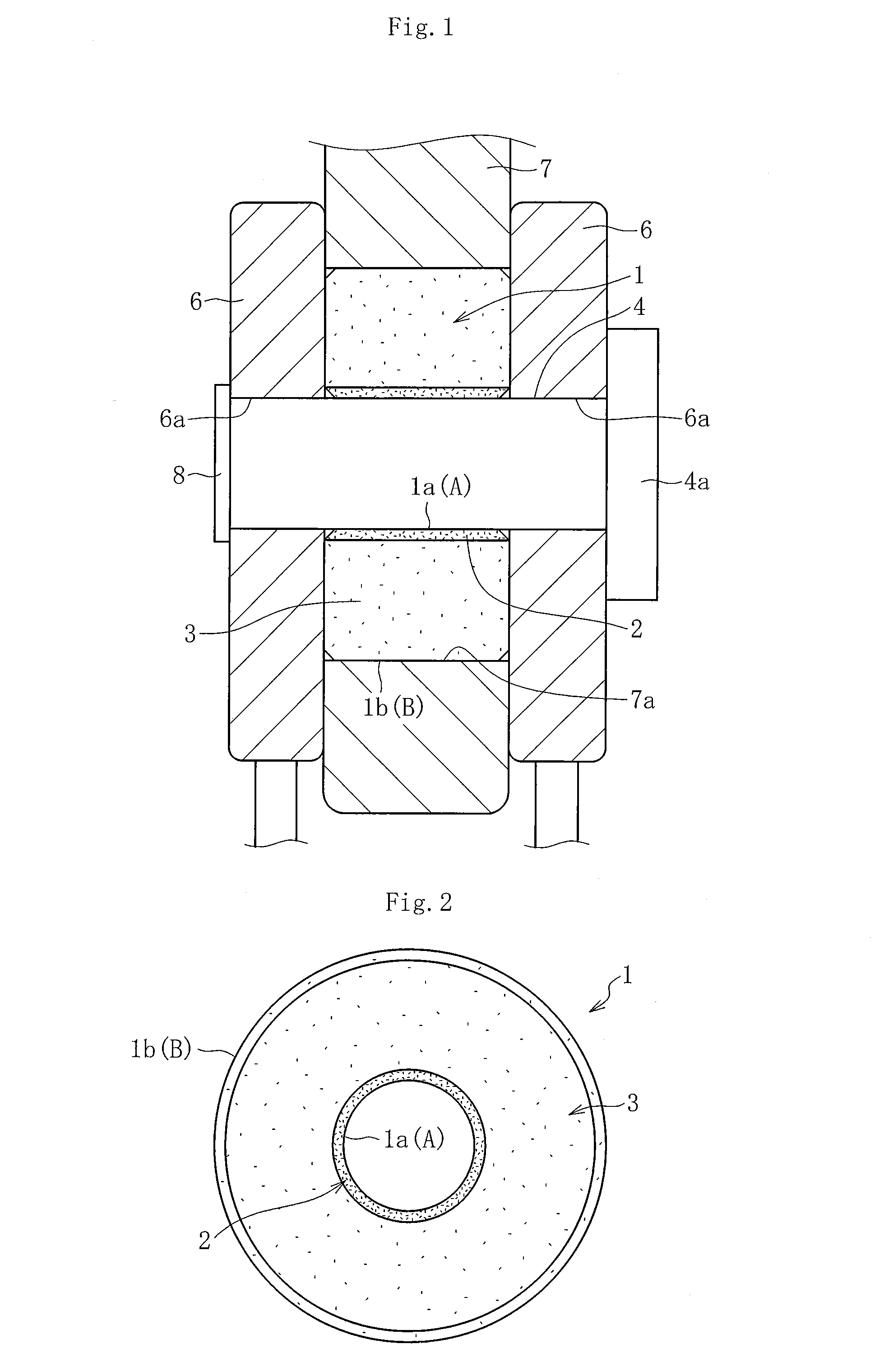
[0085]In the second embodiment described above, the sintered bearing 1 comprises the sliding layer 2 and the base layer 3 having the compositions different from each other. However, as illustrated in FIG. 18, the sintered bearing 1 may comprise three layers different from each other in composition. The sintered bearing 1 illustrated in FIG. 18 comprises not only the sliding layer 2 and the base layer 3 but also a radially inner layer 5 sintered together with the sliding layer 2 and the base layer 3. Each of the sliding layer 2 and the radially inner layer 5 is formed into the semi-cylindrical shape, and the base layer 3 is formed into a cylindrical shape. The sliding layer 2 and the radially inner layer 5 are continuous with each other in a circumferential direction. The sliding surface A of the sliding layer 2 and an inner peripheral surface of the radially inner layer 5 each have the semi-cylindrical-sur...
fourth embodiment
[0086]Next, description is made of a fourth embodiment of the present invention.
[0087]FIG. 19 and FIG. 20 are respectively a horizontal cross-sectional view (axially orthogonal cross-sectional view) and a vertical cross-sectional view (axially parallel cross-sectional view) for illustrating a sintered bearing 1 according to the fourth embodiment. This sintered bearing 1 is made of a metal sintered compact having a cylindrical shape in general, and is used, for example, at the joint portion of the arm of the construction machinery illustrated in FIG. 1. The inner peripheral surface 1a of the sintered bearing 1 is formed into a cylindrical surface shape so that the shaft 4 (such as a coupling pin configured to couple the arms to each other) inserted along the inner periphery is supported in a relatively rotatable manner by the inner peripheral surface 1a having the cylindrical surface shape. In this embodiment, the inner peripheral surface 1a of the sintered bearing 1, which has the c...
PUM
| Property | Measurement | Unit |
|---|---|---|
| friction coefficient | aaaaa | aaaaa |
| temperature | aaaaa | aaaaa |
| melting point | aaaaa | aaaaa |
Abstract
Description
Claims
Application Information