Planar lighting device

a planar lighting and sidelight technology, applied in the direction of optical light guides, instruments, optics, etc., can solve the problems of insufficient bonding strength of each small piece of double-sided tape, difficulty in reliably and stably fixing small pieces of double-sided tape to the fpc in a manner separated from one another, and difficulty in ensuring the stability of the adhesive area of the fp

Active Publication Date: 2016-07-28
MINEBEAMITSUMI INC
View PDF6 Cites 2 Cited by
  • Summary
  • Abstract
  • Description
  • Claims
  • Application Information

AI Technical Summary

Benefits of technology

[0069]The configuration described above meets demands in mounting and / or optical characteristics for an arrangement configuration of the fixing member that fixes the circuit board provided with the point light sources to the light guide plate. It is thus possible to stably and reliably fix the circuit board to the light guide plate. Even if the number of point light sources is increased by narrowing the array pitch of the point light sources, the disclosure makes it possible to stably and reliably fix the circuit board to the light guide plate with the fixing member. As a result, the disclosure can be attributed to an increase in the luminance of the planar lighting device based on an increase in the number of point light sources.

Problems solved by technology

Especially in arrangement of a double-sided tape suitably used as an adhesive member on flexible printed circuits (FPC) suitably used as a circuit board in a planar lighting device, however, it is difficult to reliably and stably fix small pieces of the double-sided tape to the FPC in a manner separated from one another because of the following reasons 1) to 3).
1) The area of each small piece of the double-sided tape (that is, the adhesive area to the FPC) is too small to secure sufficient bonding strength to the FPC.
This processing order may possibly result in reduced workability in the process of manually fixing the small pieces of the double-sided tape to the FPC, thereby making it difficult to stably fix them at uniform pressure.
If it is difficult, because of the reasons described above, to reliably and stably fix the small pieces of the double-sided tape to the FPC in a manner separated from one another, a part of the small pieces of the double-sided tape may possibly peel off the FPC when the release liner is removed after the double-sided tape is fixed onto the FPC.
Typically, if at least one of the small pieces of the double-sided tape peels off the FPC, the FPC (that is, the LEDs) fails to be stably fixed to the light guide plate.
This leads to reduction in the yield or complication of the process, such as a need for restoration.
The use of such adhesive members, however, makes it difficult to reliably and stably fix the FPC to the light guide plate.

Method used


Image

  • Planar lighting device
  • Planar lighting device
  • Planar lighting device

Examples


Embodiment Construction

[0016]Exemplary embodiments of a planar lighting device are described below in greater detail with reference to the accompanying drawings. The shape, the size, and other elements of components in the figures below are appropriately illustrated in an emphasized manner to facilitate understanding the disclosure.

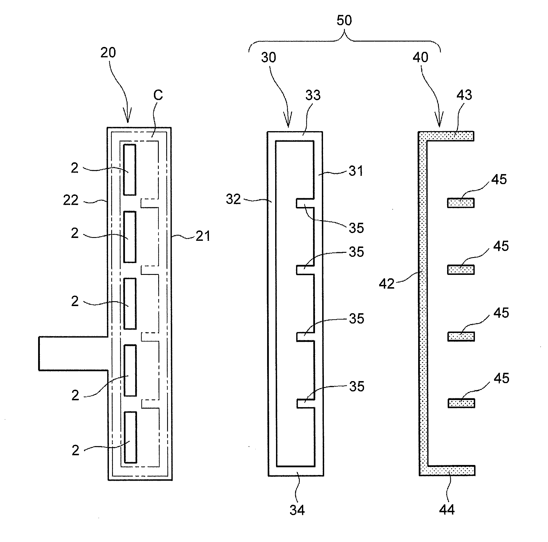
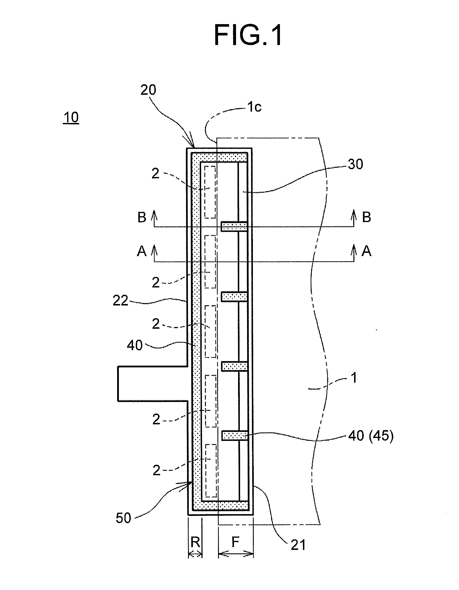
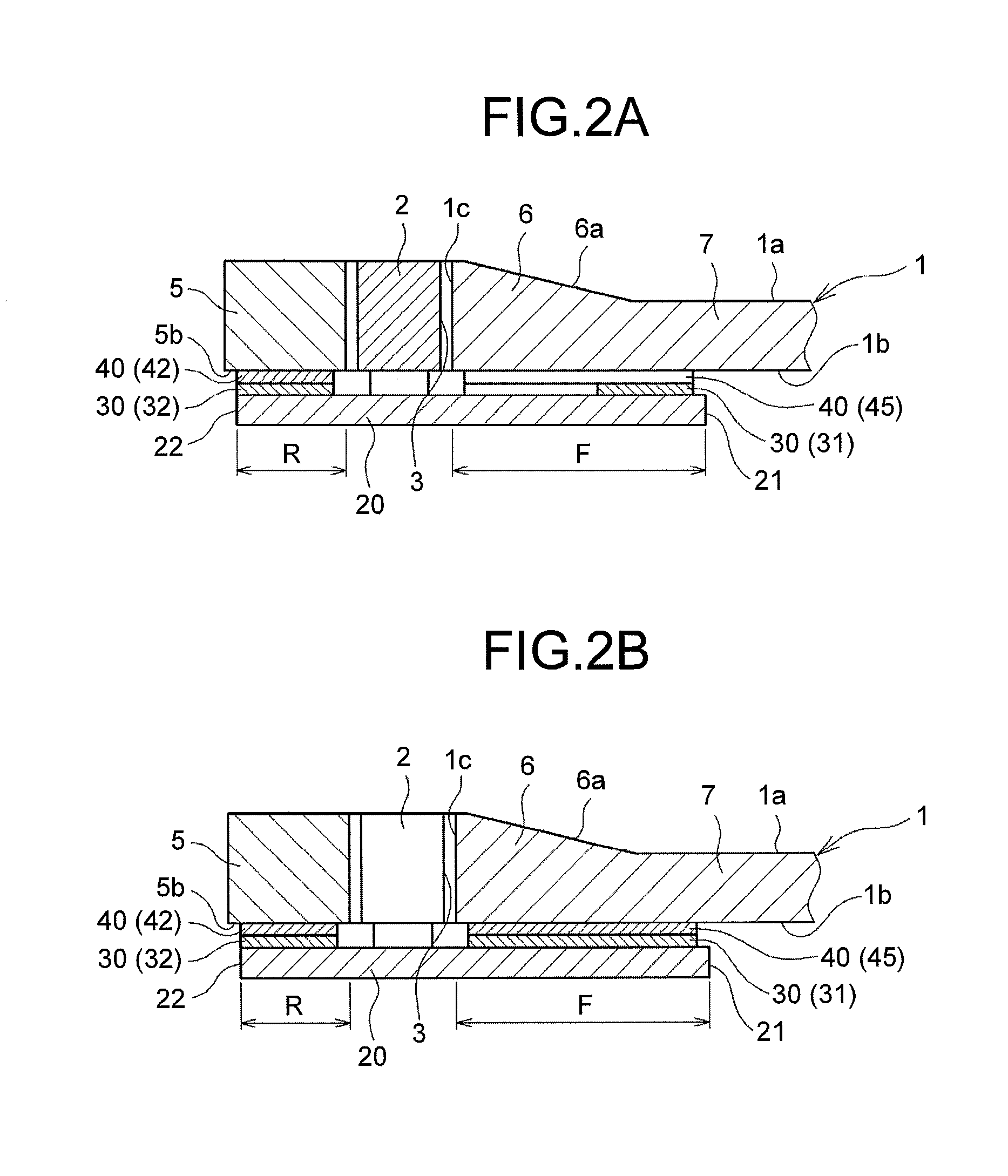
[0017]As illustrated in FIGS. 1 and 2, a planar lighting device 10 includes a light guide plate 1, a plurality of (five, in the illustrated example) point light sources 2, and a circuit board 20 on which the point light sources 2 are mounted. To facilitate understanding the disclosure, the light guide plate 1 is indicated by the alternate long and two short dashes line, and the point light sources 2 are indicated by the broken lines in FIG. 1. While the planar lighting device 10 further includes a frame-like housing frame 5 (refer to FIGS. 2A and 2B) that holds therein the planar lighting device 10 as an integrated unit, FIG. 1 does not illustrate the housing frame 5 to facilit...


PUM


Abstract

A planar lighting device includes: a plurality of point light sources; a circuit board provided with the point light sources; a light guide plate including an end surface along which the point light sources are disposed in a facing manner and a surface to which a portion of a front end of the circuit board is fixed; and a fixing member that fixes the circuit board to the light guide plate. The fixing member includes: a plurality of small-piece double-sided adhesive members; and a single-sided adhesive member that integrates the plurality of small-piece double-sided adhesive members.

Description

CROSS-REFERENCE TO RELATED APPLICATION(S)[0001]The present application claims priority to and incorporates by reference the entire contents of Japanese Patent Application No. 2015-014534 filed in Japan on Jan. 28, 2015.BACKGROUND OF THE INVENTION[0002]1. Field of the Invention[0003]The disclosure relates to a sidelight planar lighting device.[0004]2. Description of the Related Art[0005]Sidelight planar lighting devices (backlights) are widely used as lighting units for liquid-crystal display panels especially in the field of small mobile information apparatuses, such as mobile phones. Sidelight planar lighting devices each include small and environmentally compatible light-emitting diodes (LEDs) disposed along a side end surface of a light guide plate. In such planar lighting devices, the LEDs are generally mounted on a strip-like circuit board and disposed facing a light incident surface of the light guide plate. A front portion of the circuit board is fixed to a portion closer to ...

Claims


Application Information

Patent Timeline
Patent Type & Authority Applications(United States)
IPC IPC(8): F21V8/00
CPCG02B6/0091G02B6/0073G02B6/0068
Inventor KUSUNOKI, IPPEI
Owner MINEBEAMITSUMI INC
Why Eureka
Try Eureka