Touch window and display device comprising same

Active Publication Date: 2016-07-28
LG INNOTEK CO LTD
View PDF5 Cites 2 Cited by
  • Summary
  • Abstract
  • Description
  • Claims
  • Application Information

AI Technical Summary

Benefits of technology

The present patent aims to reduce the size of electronic devices' borders (also known as the "bezel") by vertically placing two wiring lines. This allows for a wider screen area and improves design. The patent also includes an intermediate layer to planarize the device's deco layer, ensure coating uniformity, and compensate for step differences, which can lead to bubbling. The intermediate layer is formed with two parts, and each part separately insulates a different wiring line. The intermediate layer helps prevent oxidation and other issues that can affect the device's reliability. Overall, the patent reduces costs, shortens process times, and improves reliability by reducing the borders between active and unactive areas.

Problems solved by technology

A deco layer for forming a logo or the like is formed in the bezel of the touch panel, and the uniformity of the electrodes formed on the deco layer cannot be guaranteed due to step difference of the deco layer and bubbles may be generated.
Accordingly, electrical characteristics may deteriorate or reliability may be lowered due to inferiorities.
Further, an in-use area of the user may be restricted on the front surface of the touch panel due to the bezel in which wiring lines that electrically connect the electrodes are disposed, which causes an inconvenience in using the touch panel.
Further, there is a limit in designing the touch panel due to the presence of the bezel.

Method used


Image

  • Touch window and display device comprising same
  • Touch window and display device comprising same
  • Touch window and display device comprising same

Examples


Embodiment Construction

[0022]Hereinafter, preferred embodiments of the present disclosure will be described with reference to the accompanying drawings.

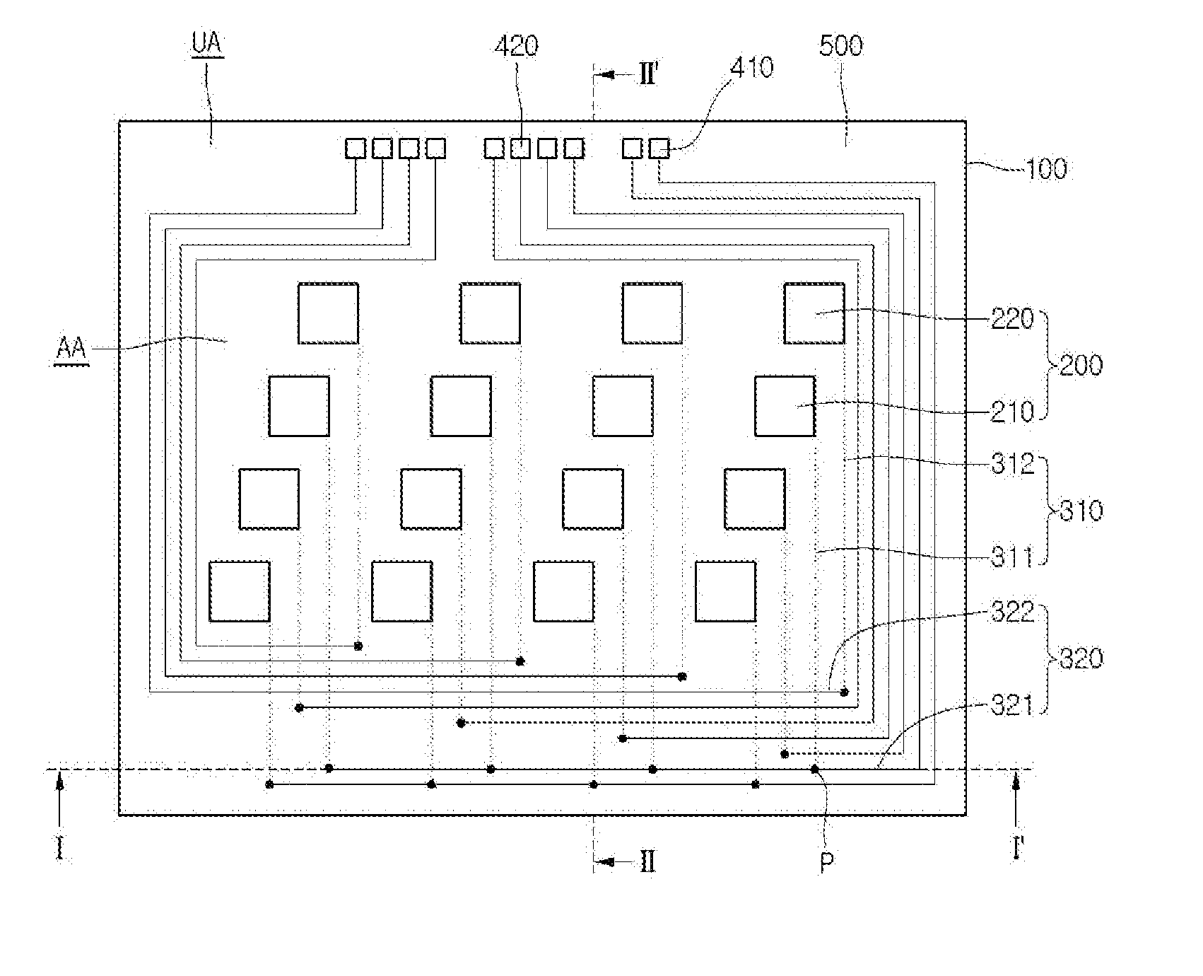
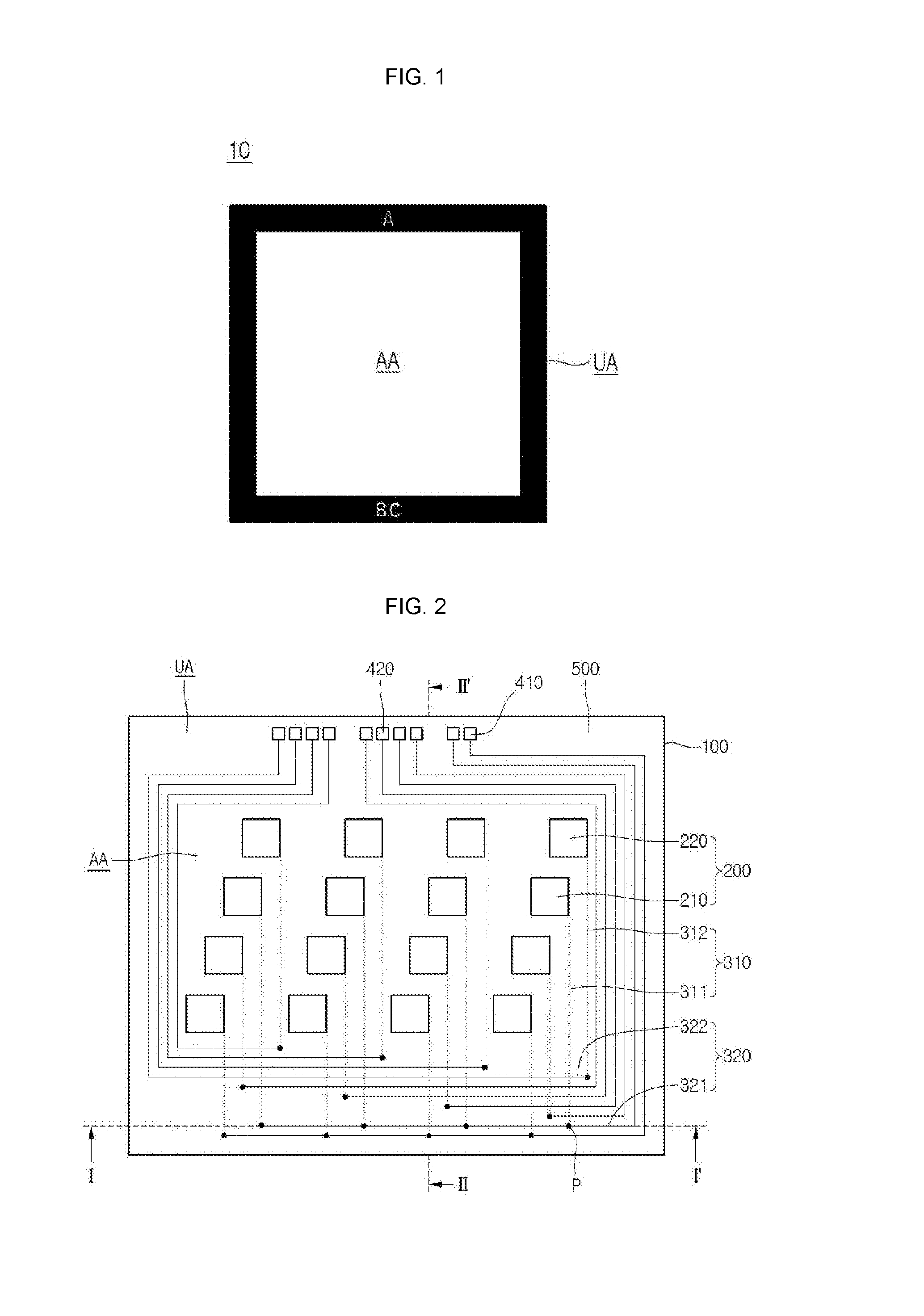
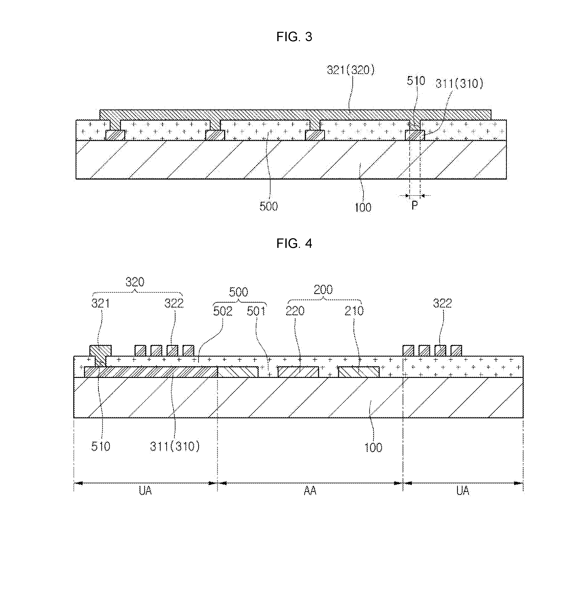
[0023]First, referring to FIGS. 1 to 4, a touch window according to a first embodiment of the present disclosure will be described. FIG. 1 is a schematic plan view of a touch window according to a first embodiment of the present disclosure. FIG. 2 is a plan view of a touch window according to the first embodiment of the present disclosure. FIG. 3 is a sectional view illustrating a section taken along line I-I′ of FIG. 2. FIG. 4 is a sectional view illustrating a section taken along line II-II′ of FIG. 2.

[0024]Referring to FIGS. 1 to 4, the touch window 10 according to the embodiment of the present disclosure includes a substrate 100 in which an active area AA in which the position of an input device (for example, a finger) is sensed and an unactive area UA disposed around the active area AA are defined.

[0025]Here, a sensing electrode 200 may be formed in t...


PUM


Abstract

A touch window according to one embodiment comprises: a substrate having an effective area and an ineffective area; a sensing electrode arranged in the effective area and sensing a position; and a wiring arranged in the effective area and the ineffective area and electrically connecting to the sensing electrode, wherein the wiring comprises a first wiring and a second wiring such that the first wiring and the second wiring are vertically arranged.

Description

TECHNICAL FIELD[0001]The embodiments of the present disclosure relate to a touch window and a display device including the same.BACKGROUND ART[0002]Recently, a touch panel, which performs an input function through the touch to an image displayed on a display by an input device such as a stylus pen or a finger, has been applied to various electronic appliances[0003]The touch panel may be typically classified into a resistive touch panel and a capacitive touch panel. In the resistive touch panel, the position of the touch point is sensed as short of an electrode occurs due to the pressure by an input device. In the capacitive touch panel, the position of the touch point is sensed by sensing the variation of capacitance between electrodes when a finger of the user touches the capacitive touch panel.[0004]A deco layer for forming a logo or the like is formed in the bezel of the touch panel, and the uniformity of the electrodes formed on the deco layer cannot be guaranteed due to step di...

Claims


Application Information

Patent Timeline
IPC IPC(8): G06F3/041
CPCG06F3/041G06F3/04164
Inventor CHOI, JOON RAKSOHN, HYUNG MINLEE, SUN YOUNGLEE, YOUNG JAEYOON, SOO KWANGLIM, HYUN SEOKCHOI, GWANG HEI
Owner LG INNOTEK CO LTD
Why Eureka
Try Eureka