
Display panel with bendable edge portion and display device including display panel thereof

Active Publication Date: 2022-06-14
WUHAN CHINA STAR OPTOELECTRONICS SEMICON DISPLAY TECH CO LTD
View PDF7 Cites 0 Cited by
  • Summary
  • Abstract
  • Description
  • Claims
  • Application Information

AI Technical Summary

Benefits of technology

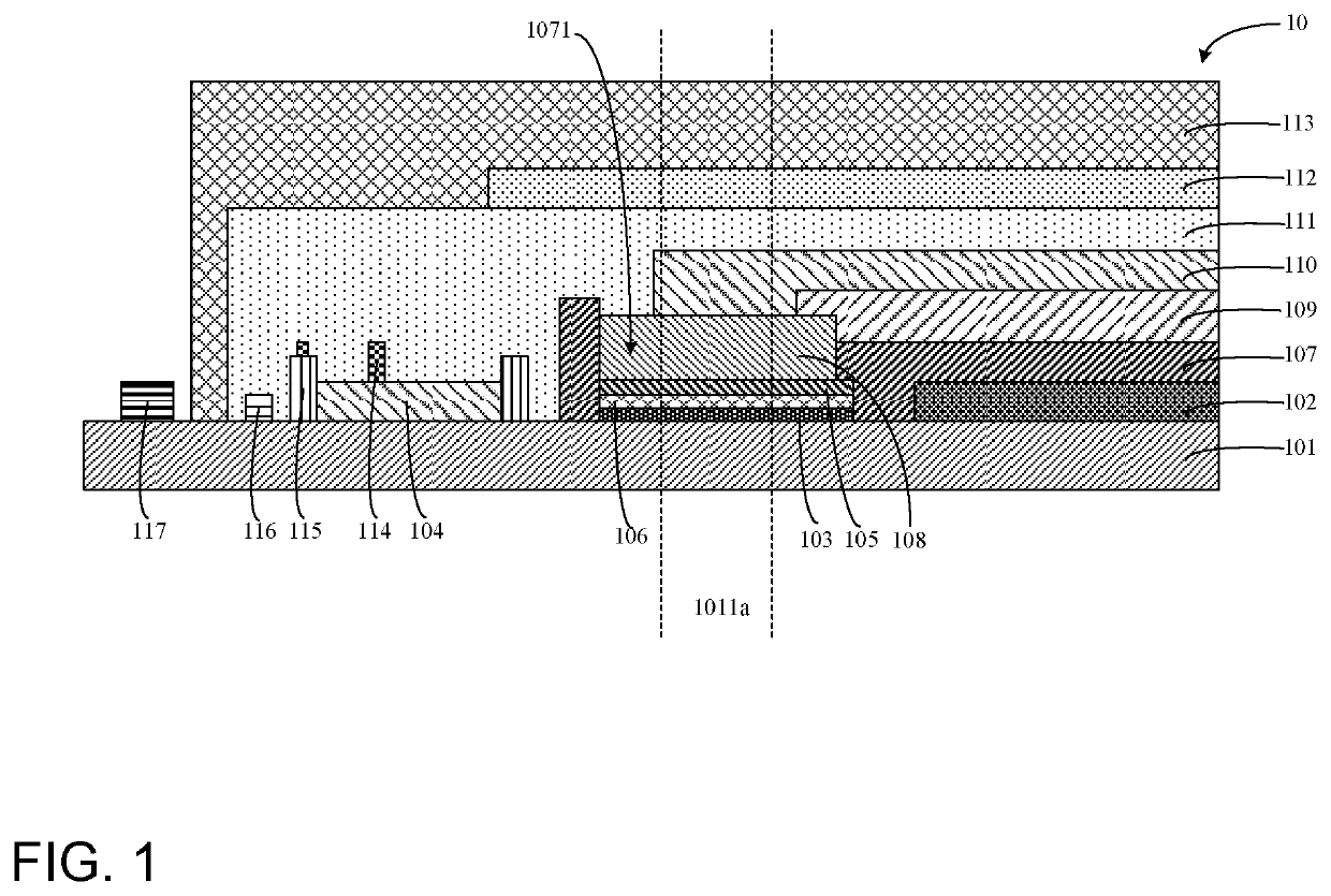
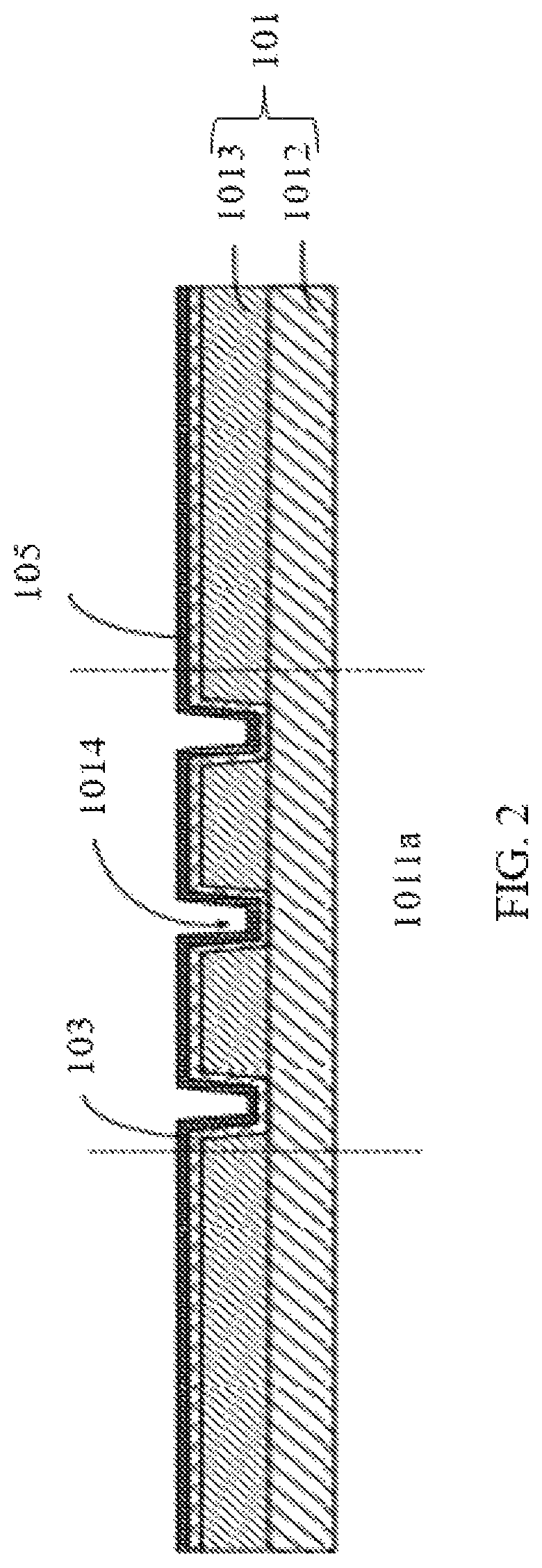
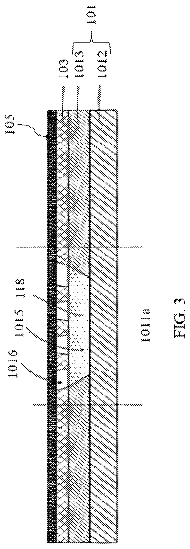
The present invention provides a display panel with a thinner bezel design. The panel includes a substrate layer, a TFT layer, a GOA drive circuit, and an auxiliary circuit. The TFT layer is located on the substrate layer, and a curved region is created near the TFT layer on the substrate layer's side. The GOA drive circuit is placed on the substrate layer and is located next to the TFT layer. The curved region is between the GOA drive circuit and the TFT layer. The auxiliary circuit is also located on the substrate layer and corresponds to the curved region. The GOA drive circuit is connected to a gate wire of the TFT layer through the auxiliary circuit. With this design, the widths of the bezels of the display panel are reduced.

Problems solved by technology

However, due to various factors, bezels of current AMOLED display panels are still rather large, which cannot satisfy user requirements.
Regarding a technical problem, bezels of current AMOLED display panels are rather large, which cannot satisfy user requirements.

Method used


Image

  • Display panel with bendable edge portion and display device including display panel thereof
  • Display panel with bendable edge portion and display device including display panel thereof
  • Display panel with bendable edge portion and display device including display panel thereof

Examples


Embodiment Construction

[0044]Hereinafter, preferred embodiments of the present disclosure will be described with reference to the accompanying drawings to exemplify the embodiments of the present disclosure, which can fully describe the technical contents of the present disclosure to make the technical content of the present disclosure clearer and easier to understand. However, the described embodiments are only some of the embodiments of the present disclosure, but not all of the embodiments. All other embodiments obtained by those skilled in the art based on the embodiments of the present disclosure without creative efforts are within the scope of the present disclosure.

[0045]An embodiment of the present disclosure provides a display panel and a display device which are described respectively below in detail.

[0046]Referring to FIG. 1, FIG. 1 is a schematic structural view showing a display panel provided by an embodiment of the present disclosure. A display panel 10 may include a substrate layer 101, a ...


PUM


Abstract

The disclosure provides a display panel including a substrate layer, a thin film transistor (TFT) layer, and a gate on array (GOA) drive circuit. The TFT layer is disposed on the substrate layer, and a bending region is disposed on at least one side of the substrate layer near the TFT layer. The GOA drive circuit is disposed on the substrate layer, and the bending region is disposed between at least one side of the TFT layer and the GOA drive circuit. The auxiliary circuit is disposed on the substrate layer and is disposed correspondingly to the bending region.

Description

RELATED APPLICATIONS[0001]This application is a National Phase of PCT Patent Application No. PCT / CN2019 / 123980 having International filing date of Dec. 9, 2019, which claims the benefit of priority of Chinese Patent Application No. 201910773828.3 filed on Aug. 21, 2019. The contents of the above applications are all incorporated by reference as if fully set forth herein in their entirety.FIELD AND BACKGROUND OF THE INVENTION[0002]The present disclosure relates to the field of display technology and, more particularly, relates to a display panel and a display device.[0003]With development of active-matrix organic light-emitting diode (AMOLED) display panel technology, narrow bezel AMOLED display panels are gaining popularity. However, due to various factors, bezels of current AMOLED display panels are still rather large, which cannot satisfy user requirements.[0004]Regarding a technical problem, bezels of current AMOLED display panels are rather large, which cannot satisfy user requi...

Claims


Application Information

Patent Timeline
IPC IPC(8): H01L27/12H01L27/32
CPCH01L27/1244H01L27/1218H01L27/3276H10K59/123H10K59/1213H10K59/12H10K59/131
Inventor WU, SHAOJING
Owner WUHAN CHINA STAR OPTOELECTRONICS SEMICON DISPLAY TECH CO LTD
Learn More