Printing apparatus, control method, and non-transitory storage medium

a control method and printing technology, applied in the direction of printing, electrical apparatus, visual presentation using printers, etc., can solve the problems of incomplete cutting, and achieve the effect of reducing wasteful consumption of continuous sheets

Active Publication Date: 2016-07-28
CANON KK
View PDF0 Cites 7 Cited by
  • Summary
  • Abstract
  • Description
  • Claims
  • Application Information

AI Technical Summary

Benefits of technology

[0013]The present invention provides a technique of reducing wasteful consumption of continuous sheet.

Problems solved by technology

If the continuous sheet cut by the cutting mechanism is extremely short, like a strip, end buckling at the start of cutting or jamming of the strip into the apparatus caused by movement of the cutting mechanism may occur, resulting in incomplete cutting.
Plain portions that are unnecessary for the user and are not used for printing are individually continuously generated, wastefully consuming the continuous sheet.

Method used


Image

  • Printing apparatus, control method, and non-transitory storage medium
  • Printing apparatus, control method, and non-transitory storage medium
  • Printing apparatus, control method, and non-transitory storage medium

Examples


first embodiment

[0037]A print control method according to the first embodiment in an inkjet printing apparatus 100 for continuous sheet 1 will be described next with reference to FIGS. 3 to 5. FIG. 3 is an explanatory view showing a print state of marginless printing in which an image has a length equal to or more than a minimum cut length Lc. FIG. 4 is an explanatory view showing a print state of marginless printing in which an image has a length shorter than the minimum cut length Lc. FIG. 5 is a flowchart of the first embodiment of the present invention. The positions of broken lines in FIGS. 3 and 4 indicate cutting positions.

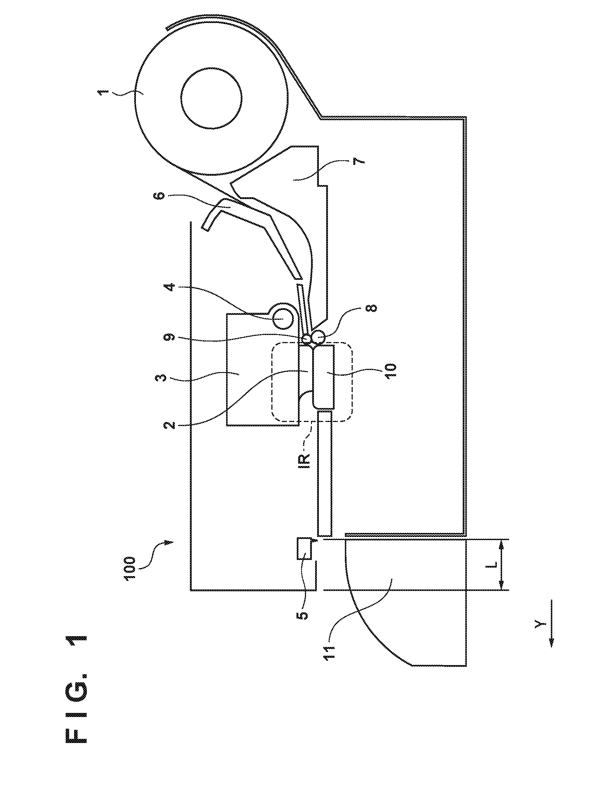
[0038]A case in which marginless printing is executed using an image length equal to or more than the minimum cut length Lc will be described with reference to FIG. 3. In FIG. 3, an arrow X indicates the main scanning direction X of a printhead unit 2, and an arrow Y indicates the conveyance direction Y of the continuous sheet 1. The downstream side (the lower side in FIG....

second embodiment

[0054]The second embodiment in which a margin to be added to a marginless image shorter than the minimum cut length is added only to the leading edge of the image will be described next with reference to FIG. 6. Note that the same reference numerals as in the first embodiment denote the same constituent elements, and a description thereof will be omitted.

[0055]First, upon receiving a marginless printing instruction for an image 20b from a printer driver 210, an inkjet printing apparatus 100 determines whether an image length Lb of the image 20b is shorter than a minimum cut length Lc. If it is revealed by the determination that the image length Lb of the image 20b is shorter than the minimum cut length Lc, the printing apparatus 100 stops adding the leading edge fed portion and instead decides to add a leading edge margin 31 to an image leading edge T of the image 20b. The printing apparatus 100 also sets a cutting position C4 to cut the leading edge margin 31 and part of the image ...


PUM


Abstract

A printing apparatus comprising: a conveying unit; a printing unit; a cutting unit; a control unit configured to, in a case in which a marginless image is to be printed, execute a first control of providing a margin portion on a front side of the image and printing the image; and a determination unit, wherein in the case in which a marginless image is to be printed, the control unit suspends execution of the first control until the determination unit determines the image.

Description

BACKGROUND OF THE INVENTION[0001]1. Field of the Invention[0002]The present invention relates to a printing apparatus, a control method of the printing apparatus, and a non-transitory storage medium.[0003]2. Description of the Related Art[0004]In a printing apparatus such as a printer, a copying machine, or a facsimile apparatus, a printhead prints, for example, an image based on image data on a printing medium supplied from a feeding unit. As the printing medium, rolled continuous sheet, a cut sheet, a plastic sheet, or the like is generally used. In particular, a printing apparatus using continuous sheet, which handles a printing medium of large size, generally includes a cutting mechanism that cuts the continuous sheet at a predetermined position after printing.[0005]If the continuous sheet cut by the cutting mechanism is extremely short, like a strip, end buckling at the start of cutting or jamming of the strip into the apparatus caused by movement of the cutting mechanism may o...

Claims


Application Information

Patent Timeline
Patent Type & Authority Applications(United States)
IPC IPC(8): G06K15/16B41J11/66H04N1/00
CPCG06K15/16B41J11/663H04N1/00676H04N1/0032B41J11/0065B41J11/70
Inventor NAGASHIMA, MASAKAZU
Owner CANON KK
Why Eureka
Try Eureka