Radio base station, radio communication system and interference notifying method in radio communication system

a radio communication system and radio communication technology, applied in the field of radio communication technology, can solve the problems of wasteful consumption of uplink frequency resources, and achieve the effect of preventing scan results and reducing wasteful frequency resources

Inactive Publication Date: 2012-04-19
HITACHI LTD
View PDF0 Cites 15 Cited by
  • Summary
  • Abstract
  • Description
  • Claims
  • Application Information

AI Technical Summary

Benefits of technology

[0013]When interference is measured using a terminal, the present invention makes it possible to appropriately select a neighboring base station, which causes strong interference, and prevents the measurement result of the base stations, for which interference measurement is not required, from being reported. In addition, the present invention prevents the scan result from being reported frequently. As a result, the present invention reduces the wasteful consumption of frequency resources when a scan result is reported from a mobile terminal.

Problems solved by technology

This frequent transmission of unnecessary information results in the wasteful consumption of uplink frequency resources.

Method used


Image

  • Radio base station, radio communication system and interference notifying method in radio communication system
  • Radio base station, radio communication system and interference notifying method in radio communication system
  • Radio base station, radio communication system and interference notifying method in radio communication system

Examples


first embodiment

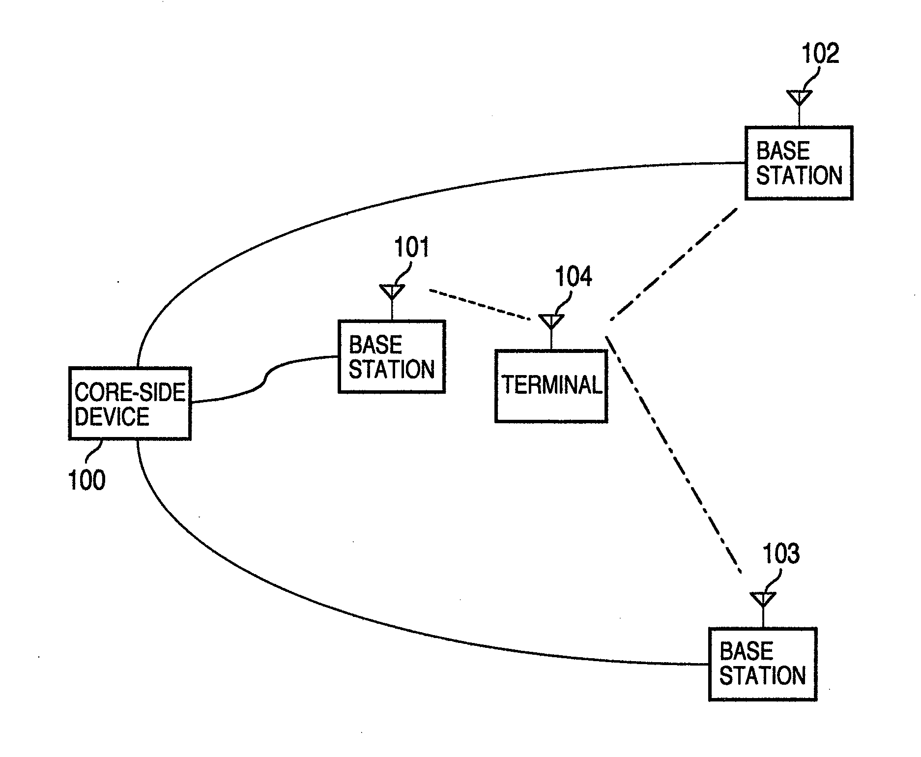
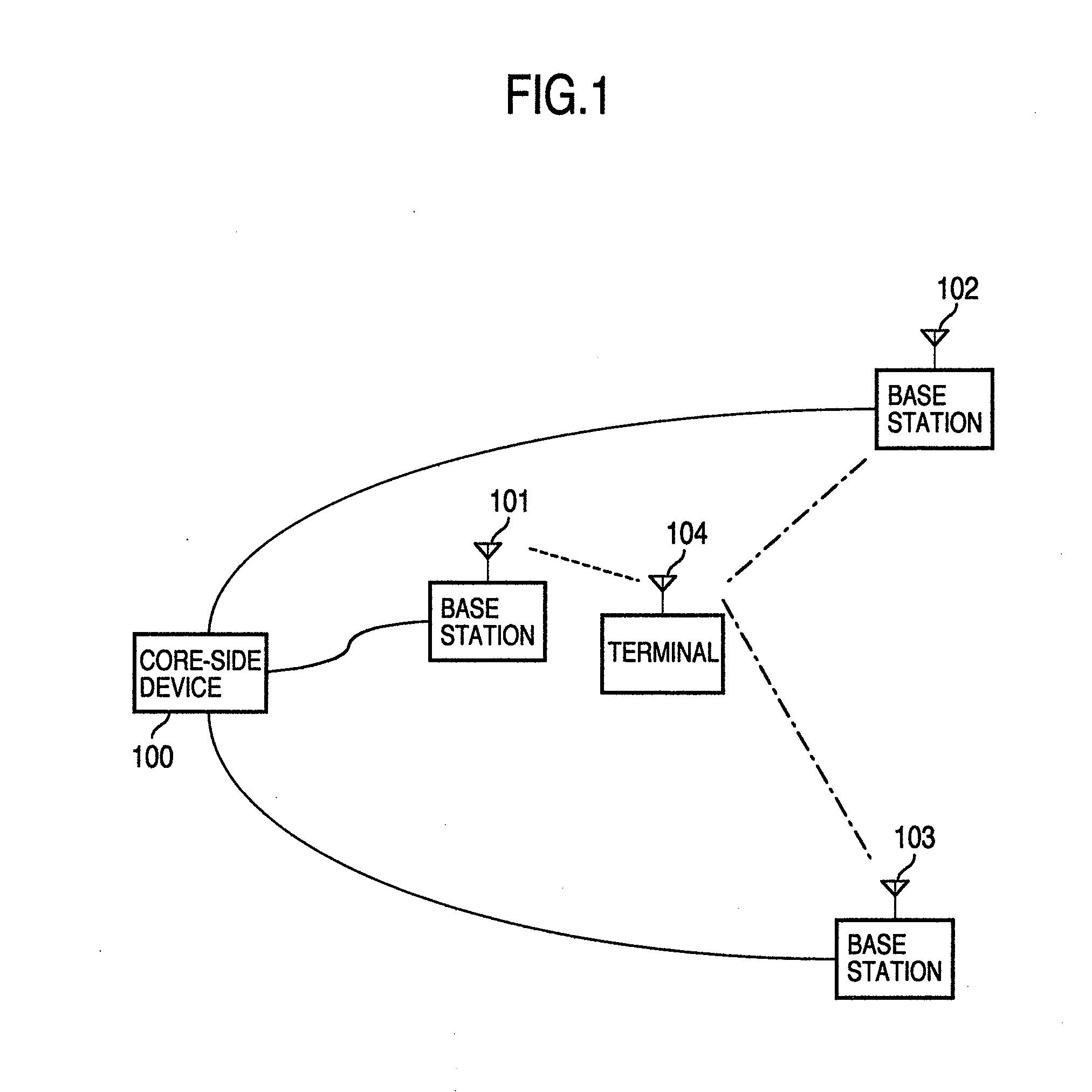
[0034]FIG. 1 is a diagram showing an example of the configuration of a radio communication system.

[0035]Base stations 101-103 are connected to the core network for data communication with a core-side device 100. The base station 101 converts information, obtained from the core-side device 100, to the high-frequency signal and transmits it to a terminal 104 via a radio signal. The terminal 104 receives the radio signal and performs the signal processing to convert the radio signal to information for carrying out communication with the core-side device 100. On the other hand, information generated by the terminal 104 is converted to the high-frequency signal by the terminal 104 and is transmitted to the base station 101 via a radio signal. The radio signal transmitted by the terminal 104 and received by the base station 101 is converted to information by the signal processing and is transmitted to the core-side device 100.

[0036]In the example shown in FIG. 1, multiple base stations 10...

second embodiment

[0087]Next, another embodiment will be described with reference to FIG. 16 to FIG. 18.

[0088]FIG. 16 is a diagram showing the cooperation among base stations in another embodiment of the present invention.

[0089]The second embodiment shows that a terminal 670 is between the neighboring base stations. The terminal 670 is connected to a base station 632.

[0090]In such a case, when a report is received from the terminal, the state of the reception signal strength of the terminal 670 is as shown in FIG. 17 as described in the first embodiment. The reception signal from the neighboring base stations 642 and 662, which are near to the terminal 670, is strong while the reception signal from the neighboring base stations 602, 622, and 652, which are distant from the terminal 670, is weak. Based on this result, the base station 632 not only creates an interfering base station list of the base stations that use the same frequency but also sets priority on the entries of the interfering base stat...


PUM


Abstract

A radio communication system is provided in which, based on a measurement condition and neighbor information specified by a base station to which a mobile terminal is connected, the mobile terminal measures the reception quality of the neighboring base stations included in the neighbor information and, when a transmission request is received from the connected base station, transmits the measurement result to the connected base station. In this radio communication system, the base station transmits neighbor information, which specifies the base stations for which interference measurement is to be performed, and a measurement result transmission request to the mobile terminal at a predetermined time for measuring the interference of neighboring base stations and, in response to it, the mobile terminal transmits the measurement result of the base stations, specified by the base station for measuring the interference, to the base station.

Description

INCORPORATION BY REFERENCE[0001]The present application claims priority from Japanese application JP2010-232086 filed on Oct. 15, 2010, the content of which is hereby incorporated by reference into this application.BACKGROUND OF THE INVENTION[0002]The present invention relates to a radio communication technology, and more particularly to a technology for reducing interference among base stations in a cellular radio communication system.[0003]In a cellular radio communication system, multiple base stations or antennas are geographically dispersed and a radio communication service area is formed in a range in which the radio waves from the base stations and the antennas are received. A mobile terminal, which is capable of receiving signals from multiple base stations and antennas, is controlled so that the mobile terminal is connected to the base station from which the highest-quality signal is received. A radio communication system provides a mechanism, called a handover, via which a...

Claims


Application Information

Patent Timeline
Patent Type & Authority Applications(United States)
IPC IPC(8): H04B17/00H04W24/00H04B7/24
CPCH04W24/10
Inventor SASAYAMA, TSUKASAKUWAHARA, MIKIOFURUEDA, KOICHIROKANZAKI, HAJIME
Owner HITACHI LTD
Why Eureka
Try Eureka