Improvements to electrical connectors and their manufacture

Inactive Publication Date: 2016-08-04
CUSTOM INVESTMENTS
View PDF11 Cites 0 Cited by
  • Summary
  • Abstract
  • Description
  • Claims
  • Application Information

AI Technical Summary

Benefits of technology

[0014]It has been realized that there is an advantage in providing an electrical connector for use in connecting electrical devices for power and/or data tra

Problems solved by technology

The connector ends of the cable are relatively bulky, partly because of the size of the electrical connector employed, and partly because of the design and thickness of the plastic jacket or coating over the connector, which jacket or coating is not only used as an electrical insulator but often also serves as the grip portion when inserting/removing the connector to/from connection with the electrical device.
Modern portable personal electrical devices, particularly smartphones, tablets, palmtops, e-readers and laptops, are power hungry, having to run many applications, run colour screens, in-built cameras, illuminate their keyboards etc., and yet there is a drive to reduce their physical size, which affects battery size and ultimately battery power.
Further more, connector cables are relatively bulky, particularly if more than a very short length of cable is required.
Also, the typical round core section of a connector cable and the relatively bulky connectors create transport and storage problems, particularly when a user is travelling with minimum personal effects, few pockets or without a travel bag.
It is also very inconvenient for a user to try to find a location with a suitable connector if they need power or data transfe

Method used


Image

  • Improvements to electrical connectors and their manufacture
  • Improvements to electrical connectors and their manufacture
  • Improvements to electrical connectors and their manufacture

Examples


Embodiment Construction

[0079]Various embodiments of the present invention are hereinafter described with reference to the accompanying drawings.

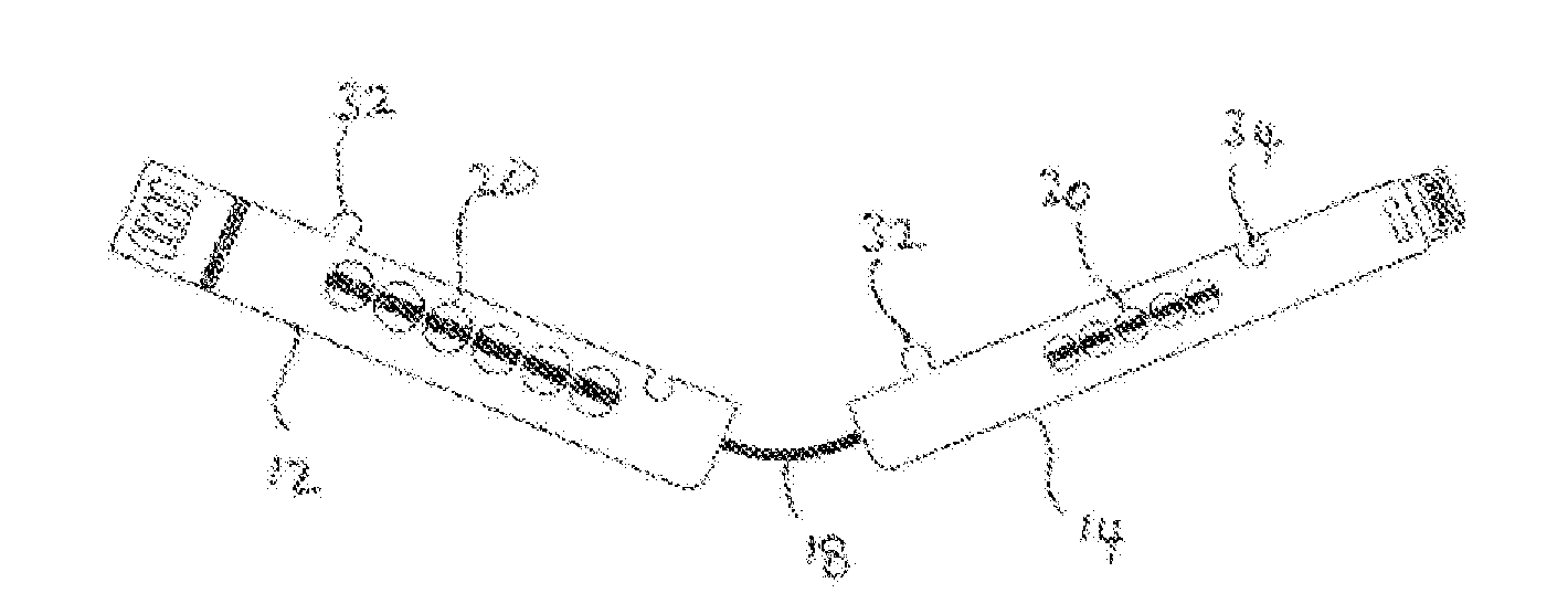
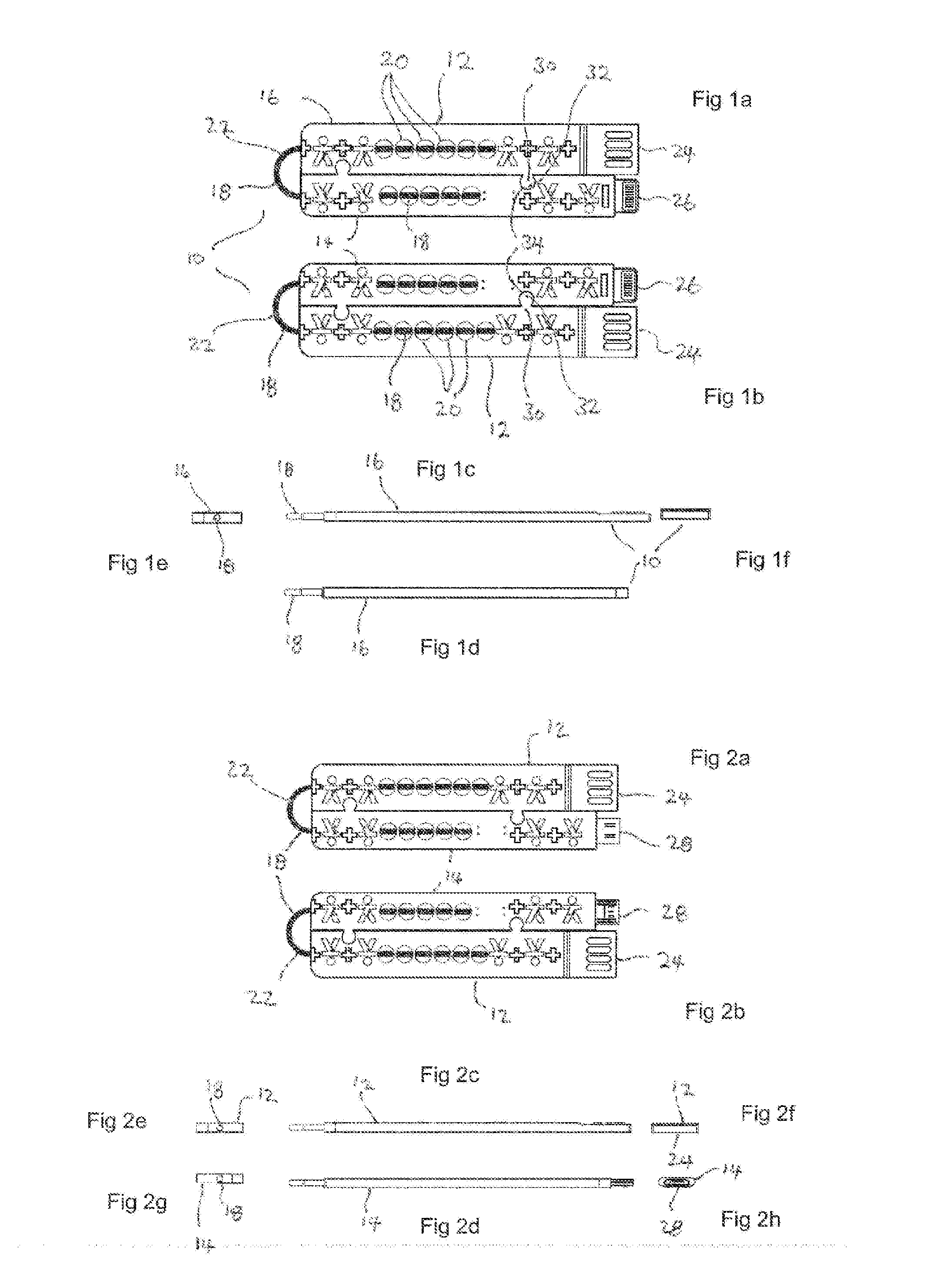
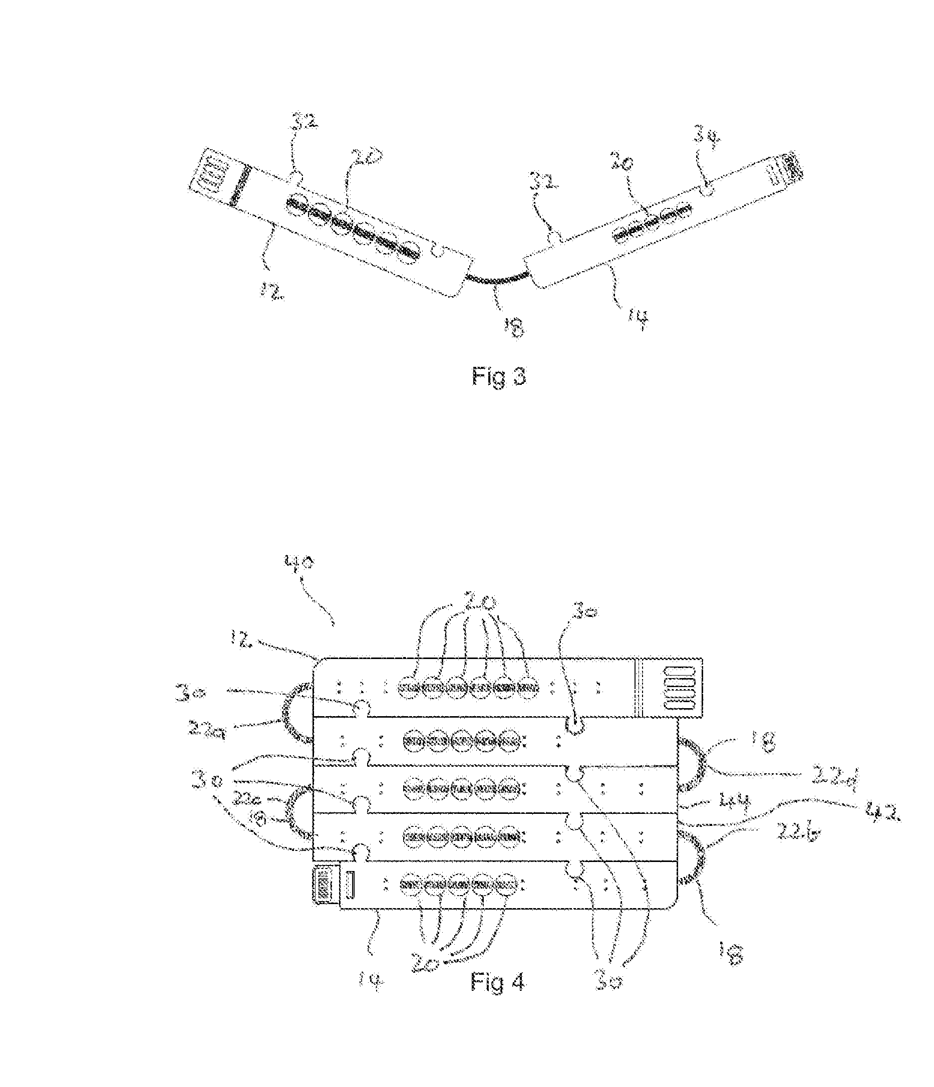
[0080]As shown in FIGS. 1a to 1f, an embodiment of the electrical connector 10 of the present invention has two portions, a first portion 12 and a second portion 14.

[0081]Each of these portions includes a protective over-moulding 16 covering a respective region of an insulated electrical conductor 18. The over-moulding is a thermoset plastic providing resilient flexibility and protection to the over-moulded regions of the electrical conductor.

[0082]Apertures 20 through the over-moulding can be sized to control the amount of desired flexibility relative to thickness and protection given by the over-moulding.

[0083]The insulated electrical conductor 18 has an exposed region 22 between the first and second portions 12,14. The insulation is a PTFE material, preferably Teflon®. The insulated region provides flexibility between the over-moulded portions thereby allowing ...


PUM


Abstract

An electrical connector (110) and a method of manufacture thereof provides an electrical end connector (112) operatively and physically connected to an electrical cable (114). A metal body portion (124) internally structurally supports a metal sleeve (130) having at least one side wall (132) and an end wall (134). Alternatively, an electrical connector (10,40) has multiple portions (12,14,42,44), which, when stored are connected laterally together, and in use can be laterally disconnected from each other though remaining longitudinally electrically connected relative to one another. The multiple portions include a protective covering over respective first and second regions of the electrical conductor, and a third region (18,22) of the electrical conductor intermediate the first and second regions being exposed from the protective coverings provided by the first and second portions.

Description

FIELD OF THE INVENTION[0001]The present invention relates to electrical connectors, such as for physically connecting one electrical device to another for power and / or data transfer.[0002]The present invention further relates to manufacture and structure of electrical connectors.BACKGROUND TO THE INVENTION[0003]Portable electrical devices are typically connected to a power source for electrical operation or battery charging, or to another electrical device for transfer of data, or both.[0004]The form of connection between one and the other is normally a flexible cable. The cable consists of an electrically conductive core extending between two electrical connectors, one at each end of the core. The core and connectors are sheathed in an insulating material, typically a plastic coating, to prevent short circuiting and to protect the core and connectors from wear and tear.[0005]The connector ends of the cable are relatively bulky, partly because of the size of the electrical connector...

Claims


Application Information

Patent Timeline
IPC IPC(8): H01R13/58H01R12/77H01R43/20H01R13/53
CPCH01R13/60H01R31/06H01R43/20H01R13/53H01R13/5845H01R12/772
Inventor SHAKIBAEE, POYASHAKIBAEE, ARASH
Owner CUSTOM INVESTMENTS
Why Eureka
Try Eureka