Liquid chromatography analysis unit
Inactive Publication Date: 2016-08-11
AGILENT TECH INC
9 Cites 0 Cited by
AI-Extracted Technical Summary
Problems solved by technology
However, such a liquid chromatography apparatus is technologically comp...
Benefits of technology
[0026]According to an exemplary embodiment of the invention, the method further comprises selecting one of a plurality of different liquid chromatography analysis units having the above-mentioned features, each of which being configured for executing a different predefined liquid chromatography analysis task, for executing a user-selected liquid chromatography analysis task for a user-defined purpose. Hence, a set of liquid chromatography analysis cartridges may be provided each of which being configured for supporting another assigned liquid chromatography analysis task. Any of these liquid chromatography analysis units may then be used with one and the same base station, depending on which liquid chromatography analysis a user presently wishes to carry out. Hence, a single multi-purpose base station may be flexibly combined by a user for a certain liquid chromatography analysis tasks. This keeps operation simple, but nevertheless expands the functionality of the system to many different liquid chromatography analysis tasks. Via different analysis task identifiers of the different liquid chromatography analysis units, the base station may self-sufficiently detect which liquid chromatography analysis task it has to support at present. The base station may have stored in a storage device thereof operation ...
Abstract
A liquid chromatography analysis unit configured for executing a predefined liquid chromatography analysis task, wherein the liquid chromatography analysis unit comprises a sample insertion compartment configured for inserting a fluidic sample to be separated, wherein the fluidic sample is to be separated when executing the liquid chromatography analysis task, a solvent accommodation section accommodating a predefined volume of at least one predefined solvent required for executing the liquid chromatography analysis task, and a sample separation unit configured for separating the fluidic sample inserted into the sample insertion compartment upon applying a solvent and sample drive force for driving the solvent and the fluidic sample through the sample separation unit.
Application Domain
Component separationSolid sorbent liquid separation
Technology Topic
SolventChemistry +1
Image
Examples
- Experimental program(1)
Example
[0033]The illustrations in the drawings are schematic.
[0034]Before, referring to the drawings, exemplary embodiments will be described in further detail, some basic considerations will be summarized based on which exemplary embodiments of the invention have been developed.
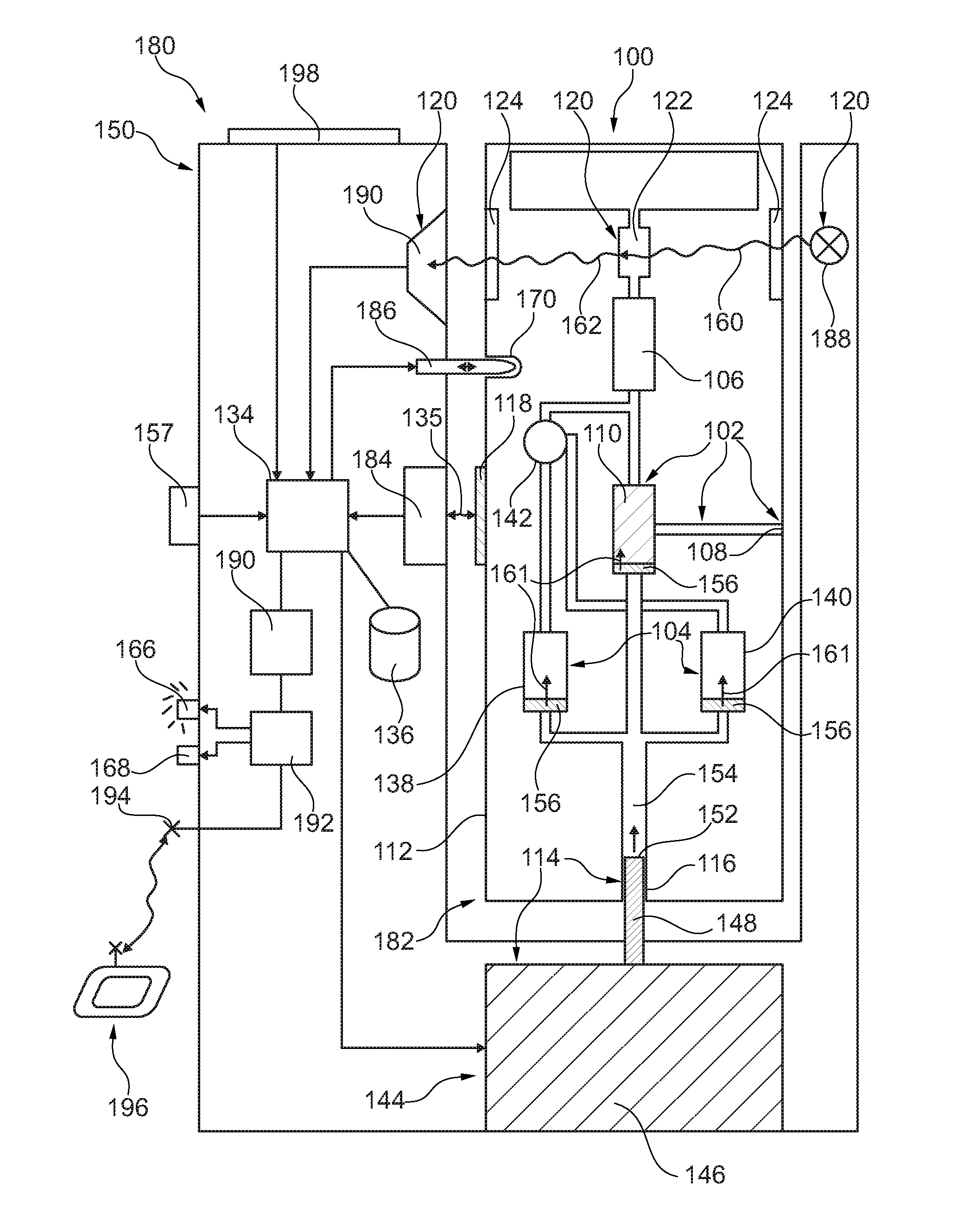
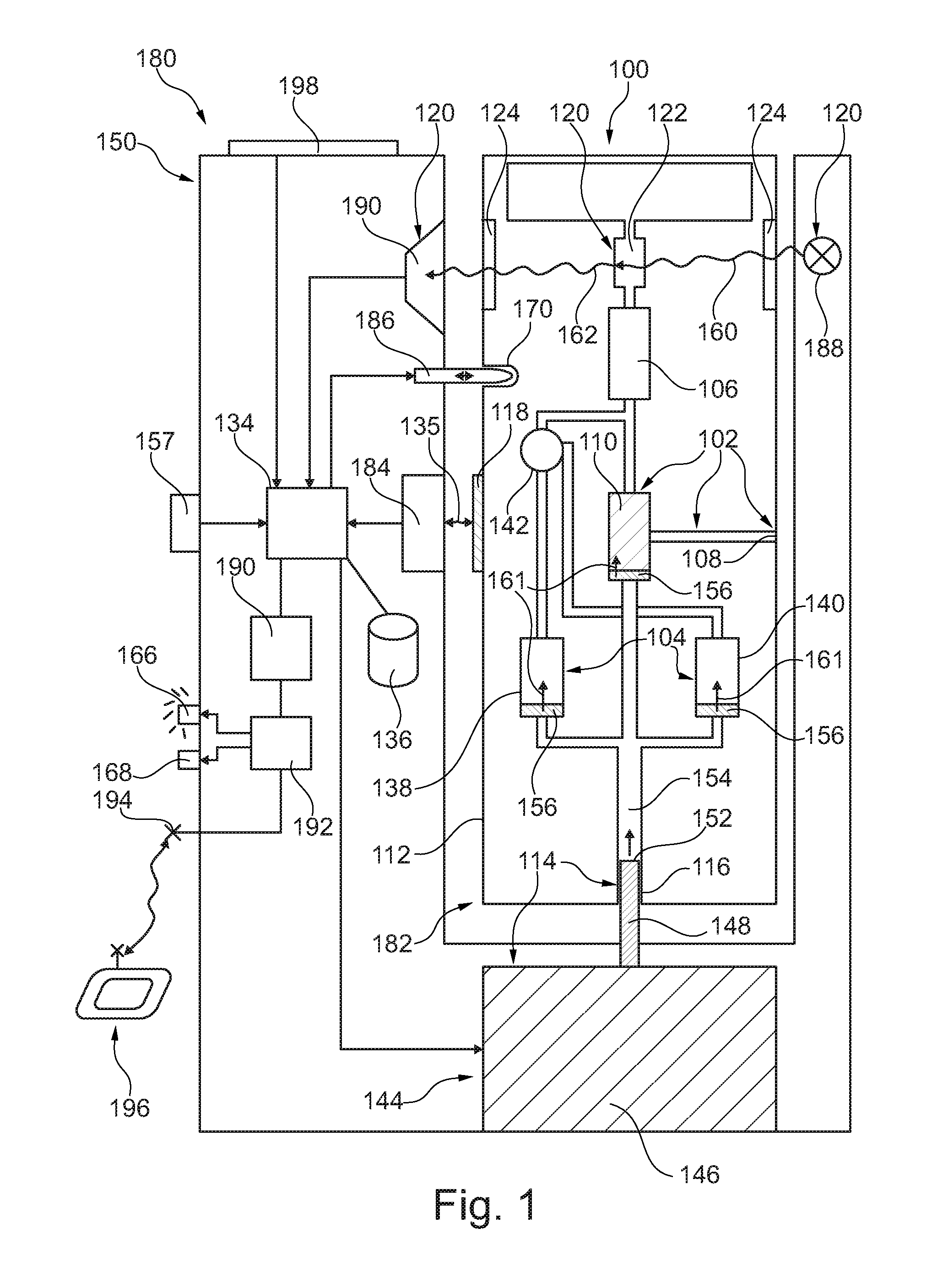
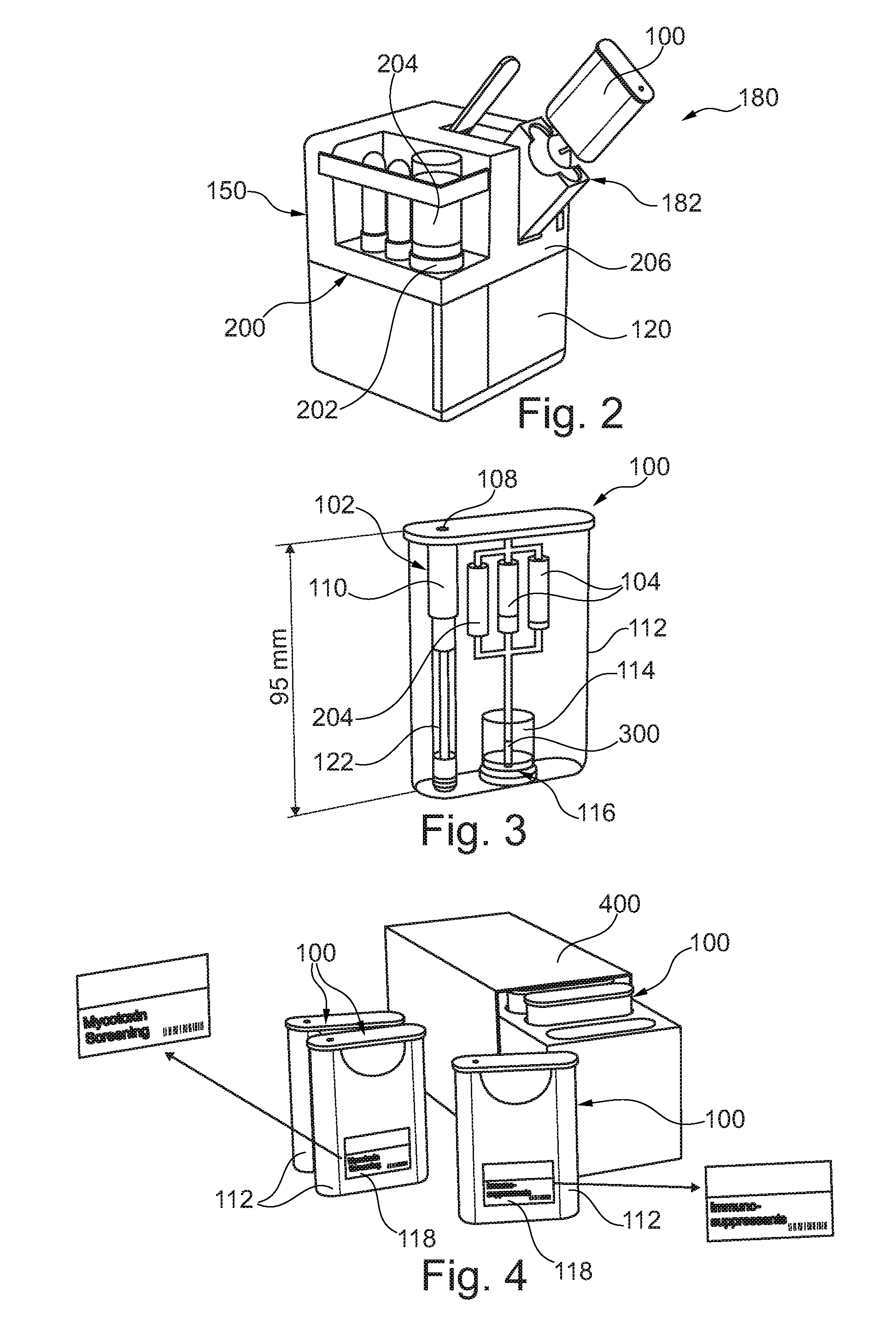
[0035]According to an exemplary embodiment, a compact HPLC (high performance liquid chromatography) analyzer cartridge is provided which can be used even by an unskilled user in a simple and flexible way.
[0036]Current standard liquid chromatography systems are huge and complicated instruments which require high education and training from the user. Many different applications are possible, but this is not always required. Errors caused by the user are easily possible.
[0037]In contrast to such complex conventional approaches, a compact liquid chromatography analyzer cartridge system according to an exemplary embodiment may be dedicated for different applications and is easy and safe to use especially from an untrained and low educated user without any HPLC background knowledge. A robust capsuled liquid chromatography analysis unit may make the conventional open handling of solvent and buffers unnecessary. All needed fluids may be built in the cartridge and may be mixed automatically, i.e. without involving the user. A traditional pump module, a traditional injection module, a traditional column compartment, as well as traditional tubes or capillaries are also not necessary according to exemplary embodiments. A liquid chromatography analysis unit configured as a compact cartridge may contain all main components for a liquid chromatography analysis which are: solvents, buffer, column, fluidic path and sample injection port. A liquid flow may be generated by a step piston which may be driven by the instrument (for example gas, compressed air or piston movement). Single and multiple injection cartridges are possible.
[0038]In one embodiment, operation of the liquid chromatography analysis unit in combination with a base station may be as follows:
[0039]1. The user puts the prepared fluidic sample, manually or by an automated system, into the liquid chromatography analysis cartridge.
[0040]2. Afterwards, the user inserts the liquid chromatography analysis cartridge into the base station (which may also be denoted as an analyzer or instrument), wherein the fluidic connections and pressure connections (if desired or required also electric connections) may be made automatically upon connection.
[0041]3. Pressure is applied to a pressure supply port of the liquid chromatography cartridge by the base station (for instance gas, compressed air or piston movement) and moves the liquids through the integrated sample separation column and connected flow path.
[0042]4. The separated fluidic sample is analyzed within the liquid chromatography cartridge or is coming out of the liquid chromatography cartridge to analyze it in an additional detection instrument.
[0043]FIG. 1 illustrates a liquid chromatography system 180 according to an exemplary embodiment of the invention constituted by two selectively connectable and disconnectable components, i.e. a portable application-specific single-use cartridge-type liquid chromatography analysis unit 100 which is only capable of executing a specific predefined liquid chromatography analysis task, and a portable multiple use and multiple purpose base station 150.
[0044]The base station 150 is configured for being removably or detachably coupled to the liquid chromatography analysis unit 100 for executing the predefined liquid chromatography analysis task. For coupling the base station 150 and the liquid chromatography analysis unit 100 to one another, the cartridge-type liquid chromatography analysis unit 100 is inserted by a user into an accommodation recess or accommodation slot as an analysis unit coupling section 182 of the base station 150. A mutually corresponding shaping of the accommodation recess and the liquid chromatography analysis unit 100 ensures that a user can only correctly insert the liquid chromatography analysis unit 100 into the base station 150. Incorrect insertion of the liquid chromatography analysis unit 100 into the base station 150 may be mechanically prevented or disabled.
[0045]The liquid chromatography analysis unit 100 is configured for only executing the predefined liquid chromatography analysis task to separate a fluidic sample by executing the predefined liquid chromatography analysis task in cooperation between the base station 150 and the liquid chromatography analysis unit 100. This means that the entire configuration for the liquid chromatography analysis unit 100 in terms of solvents, separation medium, chromatographic method and output analysis result is limited to only one single liquid chromatography analysis task (for instance determination of a specific contaminant load of certain food under test). Other liquid chromatography analysis tasks are not supported by the liquid chromatography analysis unit 100. In the described embodiment, adaptation or modification of the liquid chromatography analysis task by a user is neither possible nor allowed.
[0046]The base station 150 is configured for separating a fluidic sample to be inserted into the liquid chromatography analysis unit 100 by liquid chromatography in cooperation with the presently connected liquid chromatography analysis unit 100. An analysis task identification unit 184 (here configured as RFID reader) of the base station 150 is configured for identifying the predefined liquid chromatography analysis task (i.e. the only LC based test which can be carried out using the correspondingly configured liquid chromatography analysis unit 100) supported by the liquid chromatography analysis unit 100. In view of the limited spatial detection range (compare reference numeral 135) of the analysis task identification unit 184, the task identification can only be successfully carried out when the liquid chromatography analysis unit 100 is coupled to the analysis unit coupling section 182, i.e. is properly located within the accommodation slot. In other words, in view of the limited spatial detection range of the analysis task identification unit 184, it is advantageously only capable of reading out the analysis task identifier 118 of the liquid chromatography analysis unit 100 when the latter is received within the analysis unit coupling section 182. By taking this measure, incorrect identification events of identifying unrelated liquid chromatography analysis units 100 located in the environment of the base station 150 may be prevented. The analysis task identification unit 184 determines this information by reading out an RFID tag as the analysis task identifier 118 attached to or forming part of an exterior surface of a plastic casing 112 of the liquid chromatography analysis unit 100. The RFID tag carries the information which liquid chromatography analysis task the assigned liquid chromatography analysis unit 100 is configured to carry out. When the base station 150 has derived this information by a reading operation symbolized with reference numeral 135 in FIG. 1, a control unit 134 (such as a processor) may access a database 136 (such as a data storage device) of the base station 150 to obtain control data for controlling the liquid chromatography system 180 to execute the identified liquid chromatography analysis task. Hence, in the shown embodiment, the consumables used for executing the liquid chromatography analysis task are contributed by the liquid chromatography analysis unit 100, whereas the software for controlling the liquid chromatography analysis task is contributed by the base station 150. While executing the liquid chromatography analysis task, the fluidic sample is separated under control of the control unit 134 in cooperation between the base station 150 and the liquid chromatography analysis unit 100.
[0047]The base station 150 furthermore comprises a latch or locking mechanism 186 cooperating with a correspondingly shaped locking recess 170 of the liquid chromatography analysis unit 100 and being configured for locking the liquid chromatography analysis unit 100 to the analysis unit coupling section 182 when the coupling procedure is completed. The locking mechanism 186 can be actuated (i.e.
[0048]transferred between a locked state and an unlocked state) by the control unit 134. This allows to selectively lock (during the liquid chromatography analysis) or release (during attaching or detaching the liquid chromatography analysis unit 100 with regard to the base station 150) the liquid chromatography analysis unit 100 with regard to the base station 150.
[0049]In order to enable the liquid chromatography analysis unit 100 for executing the predefined liquid chromatography analysis task, the liquid chromatography analysis unit 100 is, in the shown embodiment, equipped with all required consumables for one analysis run. The liquid chromatography analysis unit 100 comprises a sample insertion compartment 102 configured for inserting a fluidic sample to be separated. Moreover, the liquid chromatography analysis unit 100 comprises a solvent accommodation section 104 accommodating a predefined volume of different solvents required for executing the specified liquid chromatography analysis task. A sample separation unit 106 of the liquid chromatography analysis unit 100 is configured for separating the fluidic sample inserted into the sample insertion compartment 102. To start the separation procedure, it is sufficient to apply a solvent and sample drive force to the sample and the solvents within the liquid chromatography analysis unit 100 for driving the solvent and the fluidic sample through the sample separation unit 106. The sample separation unit 106 is configured as a liquid chromatography sample separation column filled with separation medium in accordance with the predefined liquid chromatography analysis task. The mentioned procedure will be explained in the following in further detail:
[0050]The sample insertion compartment 102 comprises a sample accommodation volume 110 in fluid communication with a sample insertion interface 108. The sample insertion interface 108 allows to insert the liquid sample from an exterior of the liquid chromatography analysis unit 100 via a connection channel into the sample accommodation volume 110 of the sample insertion compartment 102. Sample insertion may be accomplished by a user who may insert the fluidic sample into the sample separation volume 110 by a manually operable insertion tool such as a syringe (not shown). The amount of sample to be filled in is defined by the value of the interior volume of the sample accommodation volume 110.
[0051]The solvent accommodation section 104 comprises two containers 138, 140, each of which being filled with a respectively predefined volume of a certain solvent. In the shown embodiment, container 138 is filled with water, whereas container 140 is filled with an organic solvent such as acetonitrile (ACN). Merely by applying pressure as described below, a solvent and sample drive force is exerted so that the solvents in the containers 138, 140 are forced to flow into a mixer 142. In the mixer 142, the solvents are mixed in accordance with a predefined mixing ratio so that a defined solvent composition is generated in accordance with the liquid chromatography analysis task to be carried out. A time-dependent functionality of the mixer 142 may be predefined in such a way that a gradient profile of time-varying solvent composition is guided towards the sample separation unit 106 merely by applying constant pressure to the containers 138, 140.
[0052]The liquid chromatography analysis unit 100 furthermore comprises a plastic casing 112 circumferentially enclosing the sample insertion compartment 102, the solvent accommodation section 104 and the sample separation unit 106 while allowing fluid communication with an exterior of the liquid chromatography analysis unit 100 via the sample insertion interface 108.
[0053]The liquid chromatography analysis unit 100 comprises a drive unit interface 116 configured for being coupled with an exterior solvent and sample drive unit 114. The latter is, in turn, configured for generating a driving force for driving the fluidic sample in the sample insertion compartment 102 to flow along a predefined fluidic path within the liquid chromatography analysis unit 100 and the solvents in the solvent accommodation section 104 when the solvent and sample drive unit 114 is coupled to the drive unit interface 116. More specifically, a bottom of the base station 150 has a recess 144 in which the solvent and sample drive unit 114 is presently inserted, and from which the solvent and sample drive unit 114 may be removed. In the shown embodiment, the solvent and sample drive unit 114 comprises a gas generation cartridge 146 capable of generating gas pressure, for instance upon receipt of a trigger signal from the control unit 134. When the solvent and sample drive unit 114 is inserted into the recess 144, a gas tube 148 of the solvent and sample drive unit 114 extends into a gas supply channel 154 of the drive unit interface 116 so that generated gas with overpressure enters via a gas supply opening 152 of the gas tube 148 into gas supply channel 154 within the liquid chromatography analysis unit 100. When an overpressure is present in the gas supply channel 154, displaceable pistons 156 in the containers 138, 140 and in the sample separation volume 110 move forwardly (i.e. upwardly according to FIG. 1, see arrows 161) and thereby press the solvent and the fluidic sample through the shown fluidic conduits and subsequently into the sample separation unit 106. Fractions of the fluidic sample will be adsorbed at the sample separation unit 106, in accordance with the principle of liquid chromatography. When the solvent composition with gradient profile subsequently flows through the sample separation unit 106, the fractions will be desorbed one after the other and will flow, as separated fractions of the fluidic sample, from the sample separation unit 106 towards a flow cell 122 of a detector 120.
[0054]The detector 120, which is embodied as electromagnetic radiation based fluorescence detector, partially forms part of the liquid chromatography analysis unit 100 and partially forms part of the base station 150.
[0055]The part of the detector 120 belonging to the liquid chromatography analysis unit 100 comprises the above-mentioned flow cell 122, and comprises detection windows 124 for externally exposing the separated fluidic sample and being transparent for electromagnetic radiation used for detecting the separated fluidic sample from an exterior of the liquid chromatography analysis unit 100. The other part of the detector 120 belonging to the base station 150 comprises an electromagnetic radiation source 188 and an electromagnetic radiation detector 190 such as a fluorescence detector. The electromagnetic radiation source 188 generates a primary electromagnetic radiation beam 160 which propagates through one of the detection windows 124 and through the flow cell 122 and thereby comes in interaction with the separated fractions of the fluidic sample flowing therethrough. By the interaction with the separated fractions of the fluidic sample, a secondary electromagnetic radiation beam 162 is generated which propagates through the other detection window 124 towards the electromagnetic radiation detector 190. The electromagnetic radiation detector 190 generates a detection signal as a raw analysis result which is forwarded to the control unit 134.
[0056]The only actions a user has to take for executing the liquid chromatography analysis task are to select an appropriate liquid chromatography analysis unit 100 fulfilling this liquid chromatography analysis task, inserting the fluidic sample into the sample insertion compartment 102, inserting the cartridge-type liquid chromatography analysis unit 100 in the analysis unit coupling section 182 of the base station 150, inserting the solvent and sample drive unit 114 into the recess 144 of the base station 150 and pressing a start button 157 (or actuating any other analysis start actuator) for triggering the control unit 134 for starting the separation.
[0057]The base station 150 furthermore comprises an evaluation unit 190 configured for evaluating a result of a detection of the separated fluidic sample. For instance, the evaluation unit 190 uses the raw analysis results as received from the detector 120 and calculates or estimates an analysis result, for instance being merely indicative of whether or not a fluidic sample has passed or failed a certain test in accordance with the liquid chromatography analysis task (for instance, a food sample has passed the test when a determined contaminants load is below a predefined threshold level, and has failed the test when the determined contaminants load is above the predefined threshold level).
[0058]The base station 150 moreover comprises an output unit 192 configured for outputting a human perceivable signal indicative of a result of the separation of the fluidic sample, in the present example an optical output. The optical output is made by controlling either a green LED 166 or a red LED 168 to emit light. For instance, when the food sample has passed the test, only the green LED 166 is illuminated. When the sample has failed the test, only the red LED 168 is illuminated.
[0059]The base station 150 also comprises a communication unit 194 configured for wirelessly communicating data indicative of a result of the predefined liquid chromatography analysis task applied to the fluidic sample to a portable electronic user device 196 such as a mobile phone on which a corresponding App may be installed. The result of the test can then be displayed to the user via the electronic user device 196.
[0060]Furthermore, the base station 150 comprises a user authorization section 198 configured for carrying out a user authorization test and for rejecting execution of the liquid chromatography analysis task when the user authorization test fails. The user authorization section 198 can be embodied as a fingerprint sensor.
[0061]FIG. 2 illustrates a liquid chromatography system 180 according to an exemplary embodiment of the invention. In the embodiment of FIG. 2, the base station 150 comprises a detector interface 200 configured for removably mounting a detector 120 for detecting the separated fluidic sample. In the shown embodiment, the detector 120 is completely attached to the detector interface 200 of the base station 150 so that no detector components need to implemented in the cartridge-type liquid chromatography analysis unit 100. Furthermore, the base station 150 according to FIG. 2 comprises a fluid container accommodation section 202 which is configured for accommodating a buffer container 204 accommodating a buffer which can be used when executing the predefined liquid chromatography analysis task. All components of the base station 150 are mounted on or in an exterior casing 206.
[0062]FIG. 3 illustrates a liquid chromatography analysis unit 100 according to an exemplary embodiment of the invention.
[0063]According to FIG. 3, also buffer container 204 is integrated in the liquid chromatography analysis unit 100 rather than forming part of the base station 150. A height of the liquid chromatography analysis unit 100 according to FIG. 3 is 95 mm. The height constitutes the largest dimension of the compact liquid chromatography analysis unit 100.
[0064]The fluidic sample is inserted by a user via the sample insertion interface 108 configured as manual injector. The solvent and sample drive unit 114 is partially integrated in the liquid chromatography analysis unit 100 according to FIG. 3. A gas inlet constitutes the drive unit interface 116, and a step piston 300 forms part of the solvent and sample drive unit 114.
[0065]FIG. 4 illustrates a set of liquid chromatography analysis units 100 according to an exemplary embodiment of the invention.
[0066]The various liquid chromatography analysis units 100 are stored in a storage box 400. Analysis task identifiers 118 of the individual liquid chromatography analysis units 100 indicate to a user (in alphanumerical form) and a barcode reader (in form of a machine-readable barcode) which specific liquid chromatography analysis task can be executed by the respective liquid chromatography analysis unit 100.
[0067]It should be noted that the term “comprising” does not exclude other elements or features and the “a” or “an” does not exclude a plurality. Also elements described in association with different embodiments may be combined. It should also be noted that reference signs in the claims shall not be construed as limiting the scope of the claims.
PUM


Description & Claims & Application Information
We can also present the details of the Description, Claims and Application information to help users get a comprehensive understanding of the technical details of the patent, such as background art, summary of invention, brief description of drawings, description of embodiments, and other original content. On the other hand, users can also determine the specific scope of protection of the technology through the list of claims; as well as understand the changes in the life cycle of the technology with the presentation of the patent timeline. Login to view more.
Similar technology patents
Thioamide compound and compounding method thereof
Owner:EAST CHINA NORMAL UNIVERSITY
Device environment configuration system and method, and data storage therefor
Owner:SEIKO EPSON CORP
Device for generating an axial load in a drill string assembly
PendingUS20220049560A1expand functionality
Owner:PERFOBUR GLOBAL INC
Model classification method based on frequency modulation continuous wave radar
Owner:NANJING UNIV OF AERONAUTICS & ASTRONAUTICS
Edited contents reproducing method and apparatus, and computer-readable storage medium
Owner:FUJITSU LTD
Portable, modular platform for assembling a stringed instrument
ActiveUS20190237047A1expand functionality
Owner:REDDICK IAN
Classification and recommendation of technical efficacy words
- expand functionality
- simple operation
Device for generating an axial load in a drill string assembly
PendingUS20220049560A1expand functionality
Owner:PERFOBUR GLOBAL INC
Portable, modular platform for assembling a stringed instrument
ActiveUS20190237047A1expand functionality
Owner:REDDICK IAN
Input processing method and input control apparatus
Owner:FUJITSU LTD
Packaging for stent delivery systems
Owner:MEDTRONIC VASCULAR INC +1
Method and apparatus for downloading data to portable devices
Owner:YAMAHA CORP