
Device for generating an axial load in a drill string assembly

Pending Publication Date: 2022-02-17
PERFOBUR GLOBAL INC
View PDF0 Cites 1 Cited by
  • Summary
  • Abstract
  • Description
  • Claims
  • Application Information

AI Technical Summary

Benefits of technology

The invention improves the functionality and performance of drilling rigs by optimizing the axial load on its units and rock breaking tools, reducing sticking and tool lock-in probability, stabilizing assembly motion trajectory during drilling of directional perforation channels, and improving drilling performance in ultra-small boreholes with horizontal branches. This patent introduces new characteristics to the device, such as improved efficiency and expanded functionality, by analyzing the characteristic features of the described invention and finding no known analogous solutions related to the possibility of creating several operation modes in systems analogous to DA for drilling.

Problems solved by technology

Occasional pressure changes in the vortex zone lead to ultrasonic vibrations in the drill bit.
However, due to faults caused by vibrations in telemetric system used to perform measurements and monitor drill parameters and the well bore trajectory, such devices cannot be used in a small drilling assembly.
A known drilling method [3, 4] using high-velocity jets (as the main rock crushing tool) has been applied abroad, but it turned out to be completely unprofitable.
Only a combination of mechanical and jet rock crushing mechanism has succeeded in the drilling practice, and such combination presents difficulties for placing in ultra-small well bores.
Jets intensify the drilling process but require large pressure differential and high fluid consumption, which leads to notable loss of pressure in small tubings, loss of fluid through mandrel bearing units in the small mud motors, fast wear and considerable excess hydraulic impact forces on the pay zone.
Generation of pulse jets in the drill bits requires considerable pressure changes and high consumption of the washing fluid in the drilling assembly and leads to considerable burden on the pay zones, which negatively affects the pressure connectivity in the well-formation system and, in the end, is unacceptable for solving the below stated technical objective and achieving the below stated technical results due to above mentioned reasons.
Anchorless loaders are preferable as the use of various types of anchors may hinder the removal of the cuttings, their deposition in the horizontal bore, and it may also lead to sticking.
Use of anchors in open holes, when the quality of cements is inadequate, may lead to wall caving in the anchorage points.
Due to the features of this structure, very high fluid pressure on the power piston is required to create the desired load on the tool, while the linear dimensions of the device are rather large, which is unacceptable as a solution for the below stated technical objective and as a way to achieve the below stated technical result.
Such loader design is also unacceptable for solving the technical objective presented below and for achieving the technical result described below due to above-mentioned reasons.
The detriment of the device, which prevents it from use to achieve the below described technical results, is its low reliability due to solids from the mud entering into the gaps between the movable and the flexible rods and hydraulic impacts when the plate closes the central axial channel.
The detriment of the device that prevents its use for achieving the below described technical results is that it is impossible to reset it without stopping the mud circulation, which leads to poorer bottom hole flushing quality and cuttings deposits in horizontal bore holes, as well as lack of function to generate oscillating operating modes.
A serious detriment of the device that prevents it from being used to achieve the below described technical result in ultra-small wells is a large probability of hydraulic impact in the drill string, i.e. lower drilling process reliability, which may even lead to drilling tools breakage, and the lack of function to generate oscillations in the string of required frequency and amplitude, so the probability of sticking cannot be excluded.
Another detriment of the device is its limited functionality due to the fact that it can work only in the longitudinal vibrations damping mode and does not allow for their generation when the sticking probability arises for BHA.

Method used


Image

  • Device for generating an axial load in a drill string assembly
  • Device for generating an axial load in a drill string assembly
  • Device for generating an axial load in a drill string assembly

Examples


Embodiment Construction

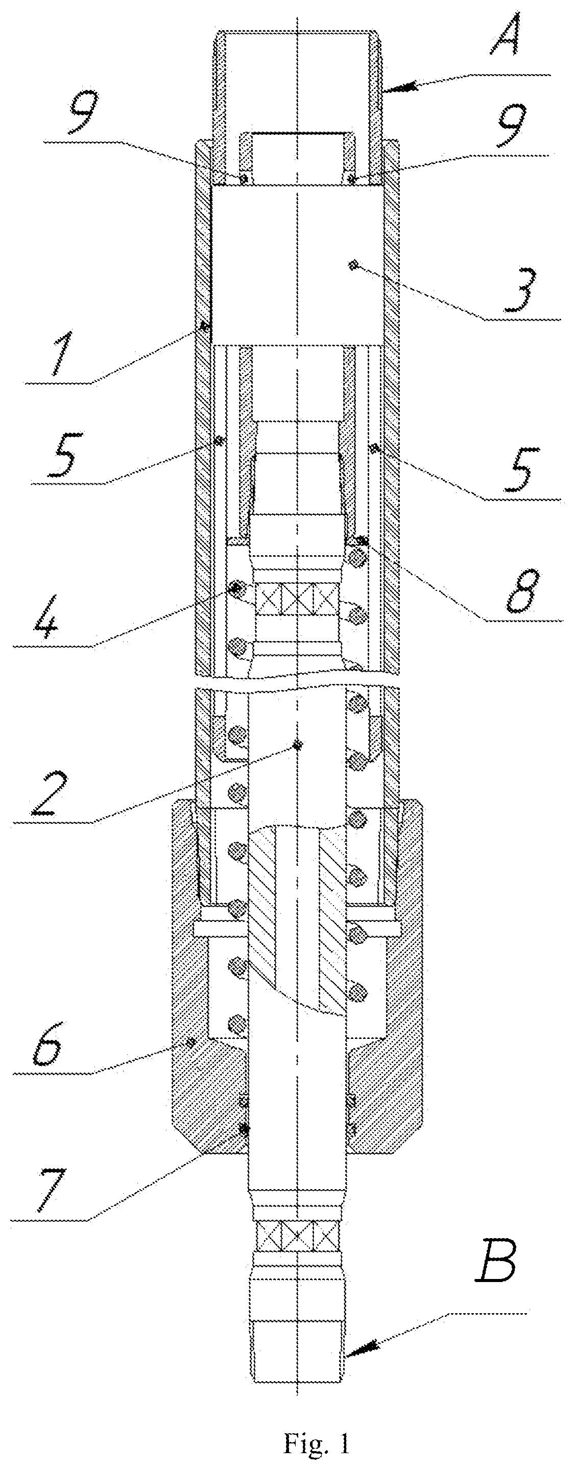
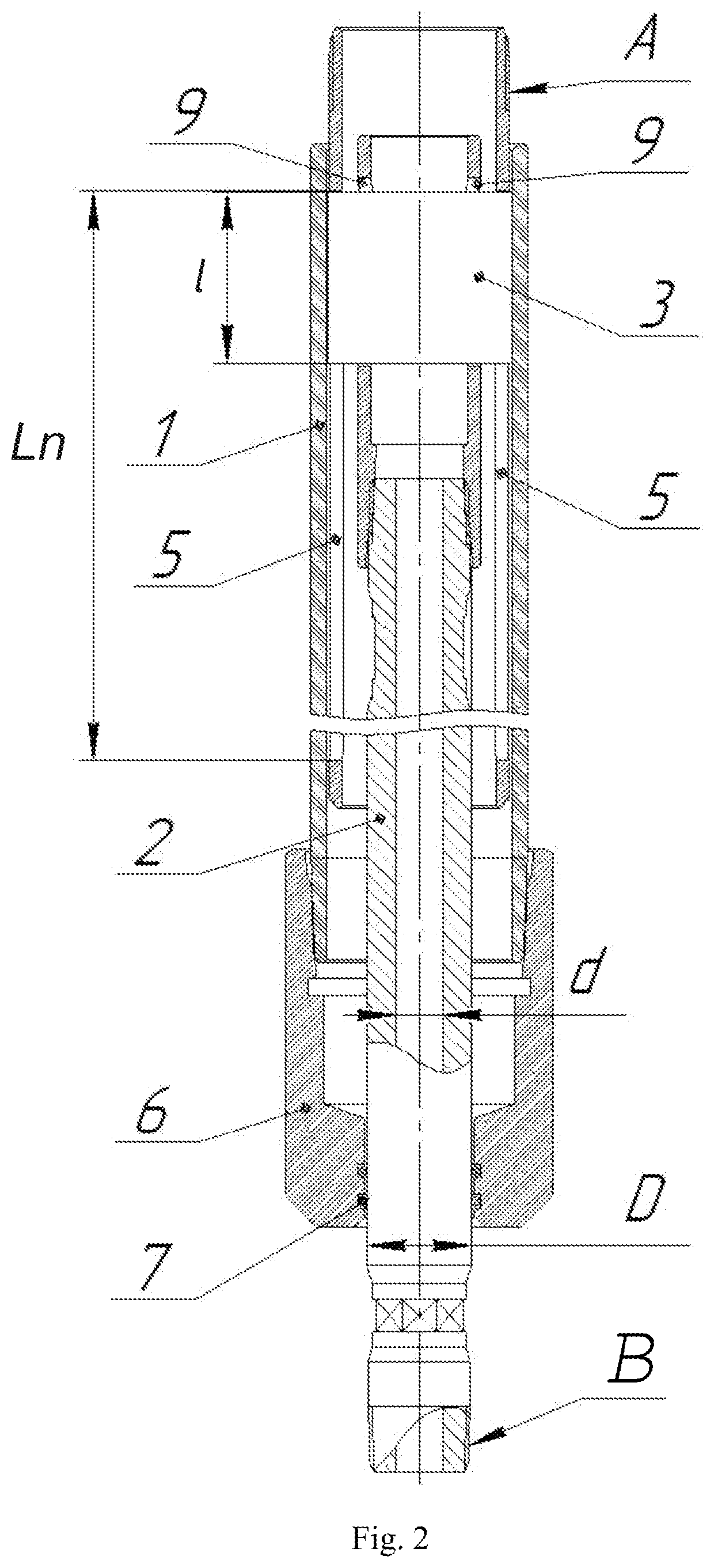
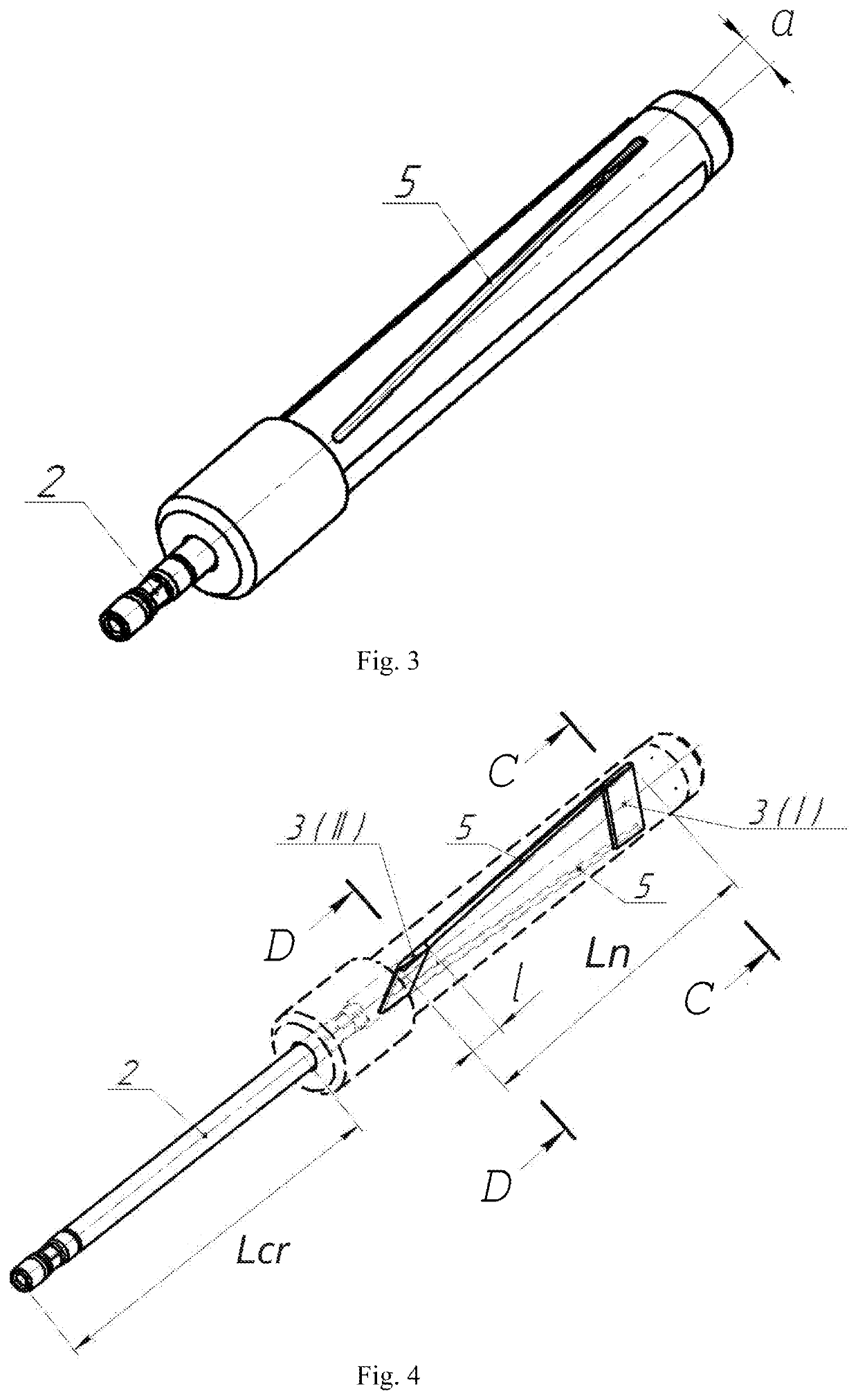
[0067]The DA operating with drilling mud and consisting of a rock-crushing tool, such as a drill bit, a small mud motor (MM), a string of coiled and rigid drill tubing, is fitted with an axial load device without anchor, for instance, between the coiled and rigid tubing, the said device including a hollow cylinder body with a sealing bush, a spring-loaded flow-type piston rod with a key, which is distinct from the existing options due to two-way longitudinal key slots on a cylinder body, along the inner generator line of the cylinder body parallel to its axis, or as a helical involute spiral with a left or right rise; in the said slots a key with longitudinal and transverse gaps and profiled surface is positioned so that it can move along the body slots together with the flow-type piston rod, and the gaps are adapted for the profiled key to have at least two degrees of freedom in the body slots and in the flow-type piston rod slots for axial movements relative to the cylinder body; ...


PUM


Abstract

The invention relates to drilling equipment. A device for generating an axial load in a drill string assembly with a bottomhole motor powered by drilling fluid comprises a hollow cylinder barrel and a spring-loaded flow-through plunger rod with a key, the rod and key forming a subassembly. The hollow cylinder barrel is provided with a sealing collar and with bilateral longitudinally oriented grooves that are arranged along the internal generatrix of the cylinder barrel and receive with longitudinal and transverse clearance the key, having a profiled surface, such that the key is capable of moving along the grooves together with the flow-through plunger rod. The length of the bilateral longitudinally oriented grooves is dependent on the maximum length of the working stroke of the flow-through plunger rod. The result is an improvement in the operating efficiency of the drill string together with expanded functional capabilities.

Description

CROSS REFERENCE TO RELATED APPLICATION[0001]The present application claims priority to International Application No. PCT / RU2020 / 000062, filed on Feb. 7, 2020, entitled “Device for generating an axial load in a drill string assembly” which is incorporated by reference herein in its entirety.PRIOR ART[0002]The invention relates to the drilling equipment, in particular, to the devices for creating optimum axial load on the rock crushing tool in a dynamic disturbance zone of the drill assembly (DA), consisting of units of different rigidity, for perforation of the producing rock in the borehole and well workover by directional drilling of branched ultra-small diameter and curvature radius channels using small mud motors in sharply varying geological setting and, correspondingly, with changing drilling modes.[0003]During the drilling, the load on the drill bit is created by the weight of the pipe string, which is rigidly connected to the bottom hole assembly (BHA) that includes a mud mot...

Claims


Application Information

Patent Timeline
IPC IPC(8): E21B19/086E21B19/089
CPCE21B19/086E21B19/089
Inventor LIAGOV, ILIALIAGOV, ALEXANDERKACHEMAYEVA, MARINA
Owner PERFOBUR GLOBAL INC
Features
  • Generate Ideas
  • Intellectual Property
  • Life Sciences
  • Materials
  • Tech Scout
  • Unparalleled Data Quality
  • Higher Quality Content
  • 60% Fewer Hallucinations
Learn More