
Endotracheal Tube Securement Device

a secure device and endotracheal tube technology, applied in the field of medical devices, can solve the problems of unfavorable patient safety, unsanitary conditions, infection,

Inactive Publication Date: 2016-08-18
UNIVERSITY OF ROCHESTER
View PDF6 Cites 6 Cited by
  • Summary
  • Abstract
  • Description
  • Claims
  • Application Information

AI Technical Summary

Benefits of technology

This patent is for a device that helps to secure an endotracheal tube in place on a patient's face. The device has two parts that fit around the patient's face and are connected at a point where the tube can be placed. There is also a movable holder for the tube, and two struts that each hold a bite wedge to keep the tube in place. This device helps to keep the tube secure and in the right position, which can make a difference in the patient's treatment.

Problems solved by technology

Tape is problematic in many ways.
For one, it does not often provide a secure retention technique, or can loosen over time as secretions build up around the tape.
Those secretions can also create unhygienic conditions and infection.
The secretions around and under the tape can cause irritation and ultimately infection.
The tape can also track secretions to other unintended areas, creating irritation and infection elsewhere.
These clamps are often large, unsightly, uncomfortable, and do not always prevent a patient from biting down on the endotracheal tube, and create difficulties in sectioning out secretions with a suction catheter due to their size and overall geometry.
Without the ability to thoroughly suction out secretions, there exists a real and serious risk for infection and pneumonia, particularly if the secretions track down the endotracheal tube, creep past the balloon and into the lungs.
Further, with both tape as well as various clamps, a patient can bite down on the endotracheal tube, damaging or pinching off the tube and creating an emergency situation.

Method used


Image

  • Endotracheal Tube Securement Device
  • Endotracheal Tube Securement Device
  • Endotracheal Tube Securement Device

Examples


Embodiment Construction

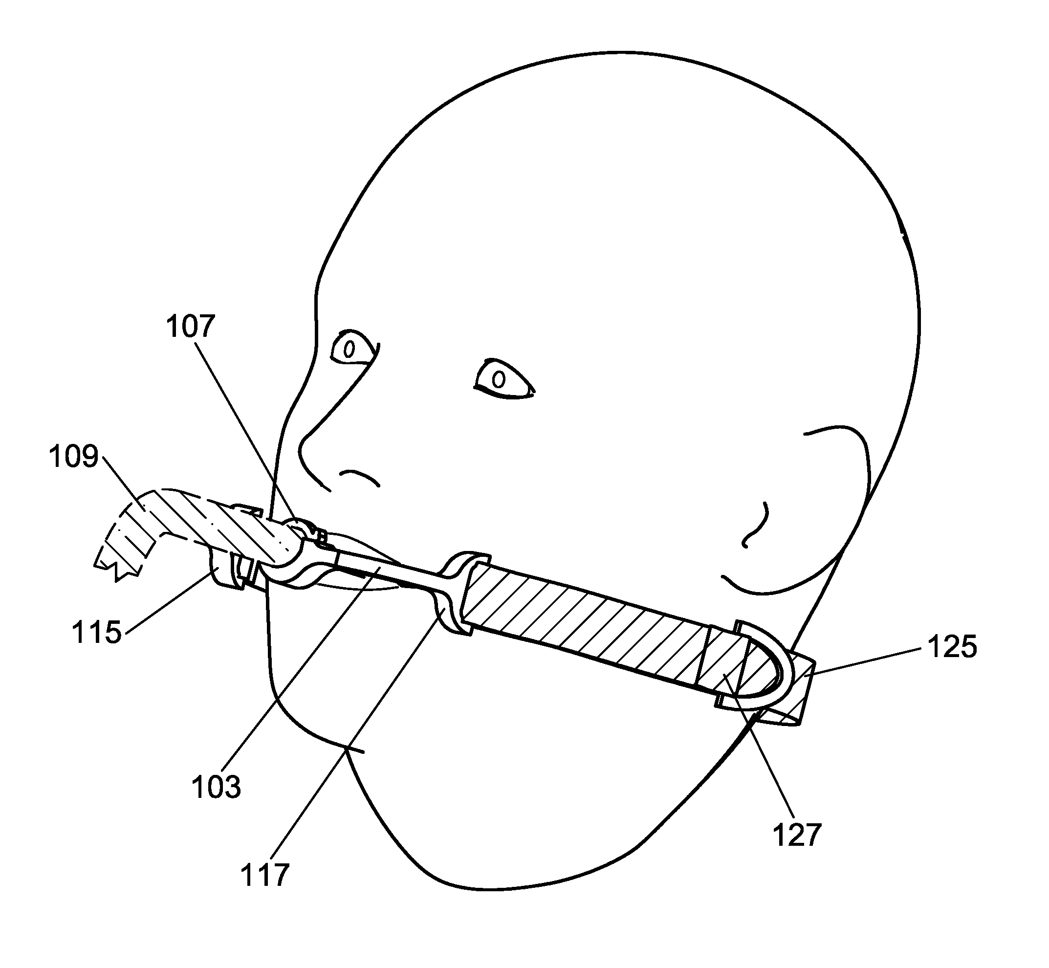
[0021]An Endotracheal Tube Securement Device is described herein. The device represents a significant improvement over the common technique of using tape or clamps for retention of an endotracheal tube.

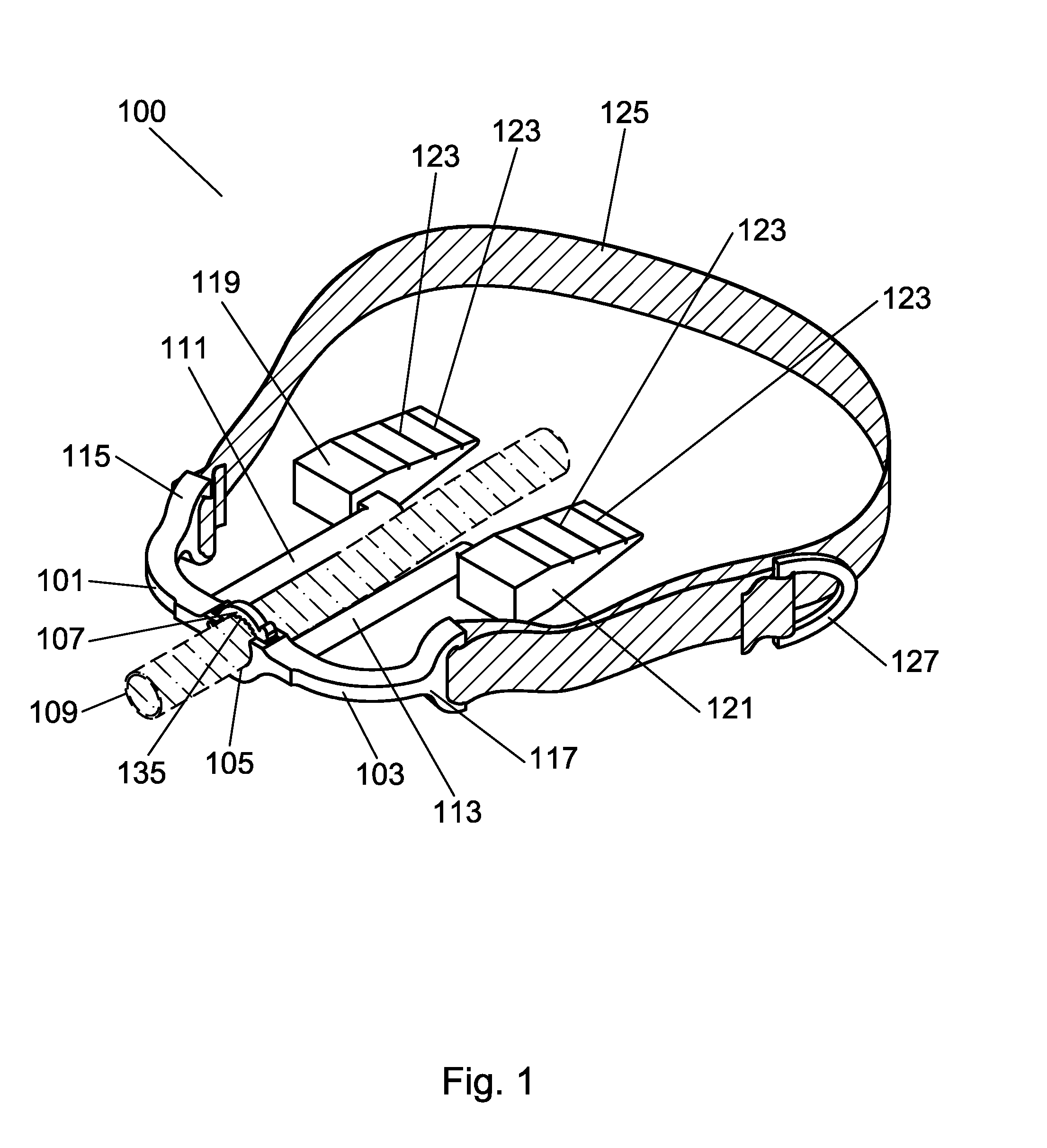
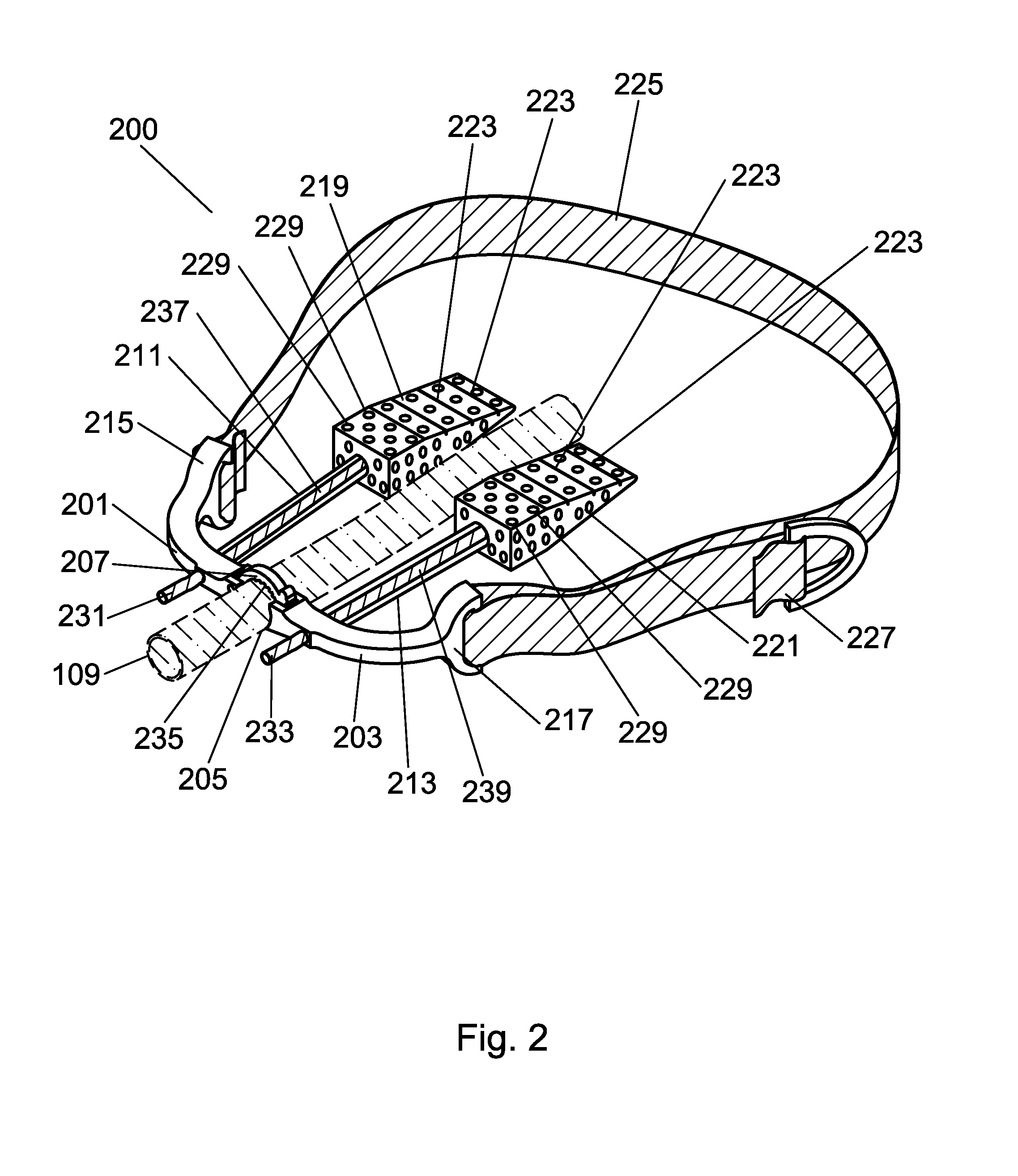
[0022]Turning first to FIG. 1, a perspective view of the Endotracheal Tube Securement Device can be seen. A first limb 101 and a second limb 103 form the primary structure of the device, and are joined or otherwise attached or manufactured together, with a tube rest 105 between each limb section. The tube rest 105 may be semi-circular or otherwise conformal to a tube 109 such as an endotracheal tube. A tube retainer 107 can also be seen above the tube rest 105, and may be hinged or otherwise movably attached to the tube rest 105 or a section of the first limb 101 or the second limb 103. The hinge, evident where the tube retainer 107 is fixed to the tube rest 105, may be a plastic or metal pin, or may be a live hinge integral with surrounding plastic of the device. The placement of the...


PUM


Abstract

An endotracheal tube securement device is disclosed. The device provides a sanitary and secure way to retain aft endotracheal tube. The device employs bite wedges to prevent a patient from biting the endotracheal tube, while providing an unobtrusive, comfortable and secure means for maintaining the endotracheal tube in place. The device is less visually traumatic than current arrangements. The device is small, with little to no facial contact, providing minimal obstruction of the oral cavity for hygiene and clinical management. The device has a first limb and a second limb joined at a junction that forms a rest for the endotracheal tube. There is a tube retainer attached to the tube rest. A first strut protrudes from the first limb to retain a first bite wedge, and a second strut protrudes from the second limb to retain a second bite wedge. A suction feature may also be provided.

Description

CROSS REFERENCE TO RELATED PATENT APPLICATIONS[0001]This application claims priority to U.S. patent application Ser. No. 62 / 116,408 filed Feb. 14, 2015 entitled “Endotracheal Tube Securement Device” by Mirza and Walsh, the entire disclosure of which is incorporated herein by reference.BACKGROUND OF THE INVENTION[0002]1. Field of the Invention[0003]The present invention relates generally to medical devices, and more particularly to an endotracheal tube securement device.[0004]2. Description of the Related Art[0005]Securing an endotracheal tube in a patient's mouth is of major importance for the well-being of a patient. During endotracheal intubation, a flexible plastic tube known as an endotracheal tube is inserted within the trachea. This procedure is often done while the patient is under deep sedation or is unconscious. With the help of a laryngoscope to provide proper visualization and to hold the tongue aside, the endotracheal tube is inserted. Most endotracheal tubes are made of...

Claims


Application Information

Patent Timeline
IPC IPC(8): A61M16/04A61M16/08
CPCA61M16/0493A61M16/0497A61M16/0463A61M16/0816A61M2209/082A61M2209/088
Inventor MIRZA, M. ZUBAIRWALSH, SARAH ELIZABETH
Owner UNIVERSITY OF ROCHESTER
Learn More