Method and apparatus for time-domain droop control with integrated phasor current control

a technology of time-domain droop control and phasor current control, which is applied in the direction of electrical apparatus, conversion without intermediate conversion to dc, and ac network circuit arrangement, etc., can solve the problems of loss of direct control of real and reactive currents, damage to converters, and affecting the operation of the converter

Active Publication Date: 2016-08-25
ENPHASE ENERGY
View PDF3 Cites 24 Cited by
  • Summary
  • Abstract
  • Description
  • Claims
  • Application Information

AI Technical Summary

Benefits of technology

[0008]Embodiments of the present invention generally relate to power converter current control substantially as shown in and / or described in connection with at least one of the figures, as set forth more completely in the claims.

Problems solved by technology

This technique has several advantages including improved dynamic response and harmonic compensation; however, the method loses direct control of real and reactive currents and thus makes it difficult to impose current limits.
For example, if the virtual source voltage phasor commanded during droop control would result in a real or reactive current phasor that exceeds the maximum capability of the converter, the converter could be damaged or be forced to shut-down.
In addition, by not having direct phasor control of the real and reactive currents, a converter cannot be operated with a virtual impedance while grid connected, resulting in disjointed transitions between islanded and grid-connected states.

Method used


Image

  • Method and apparatus for time-domain droop control with integrated phasor current control
  • Method and apparatus for time-domain droop control with integrated phasor current control
  • Method and apparatus for time-domain droop control with integrated phasor current control

Examples


Embodiment Construction

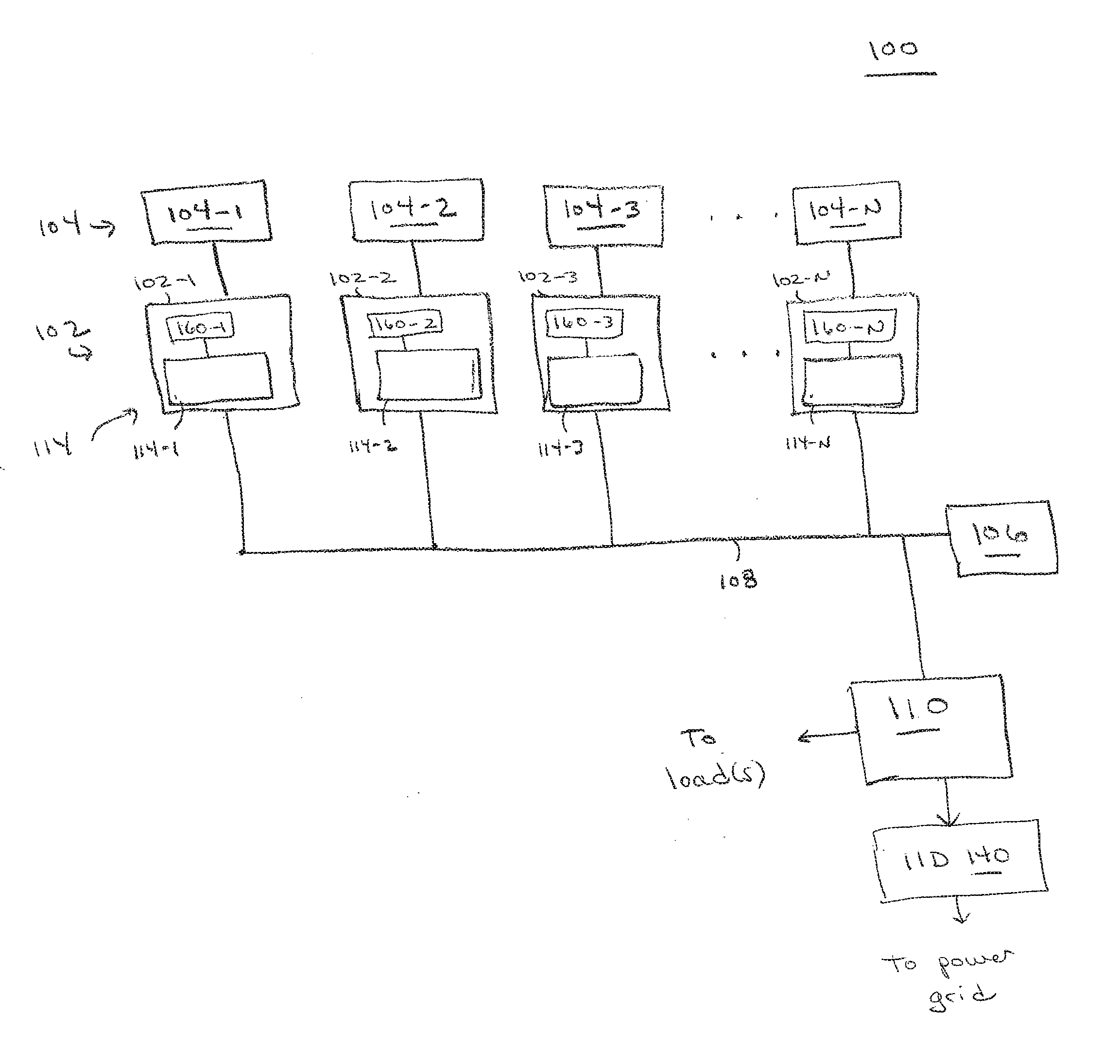
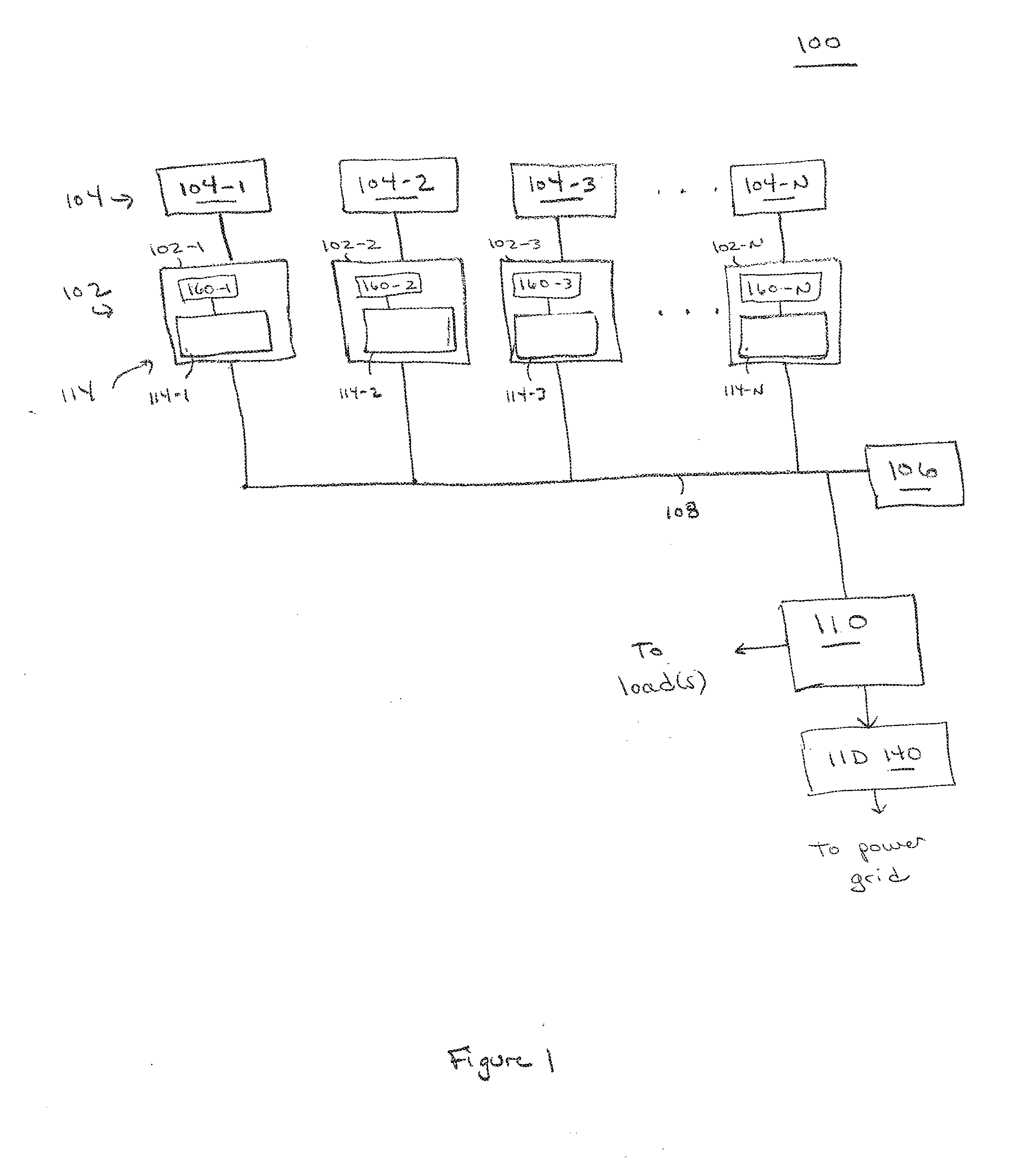
[0016]FIG. 1 is a block diagram of a system 100 for power conversion using one or more embodiments of the present invention. This diagram only portrays one variation of the myriad of possible system configurations and devices that may utilize the present invention.

[0017]The system 100 is a microgrid that can operate in both an islanded state and in a grid-connected state (i.e., when connected to another power grid (such as one or more other microgrids and / or a commercial power grid). The system 100 comprises a plurality of power converters 102-1, 102-2, 102-3 . . . 102-N, collectively referred to as power converters 102; a plurality of power sources 104-1, 104-2, 104-3 . . . 104-N, collectively referred to as power sources 104; a system controller 106; a bus 108; a load center 110; and an island interconnect device (IID) 140 (which may also be referred to as a microgrid interconnect device (MID)). In some embodiments, such as the embodiment described below, the power converters 102 ...


PUM


Abstract

A method and apparatus for power converter current control. In one embodiment, the method comprises controlling an instantaneous current generated by a power converter such that that power converter appears, from the perspective of an AC line coupled to the power converter, as a virtual AC voltage source in series with a virtual impedance, wherein real and reactive phasor currents for the power converter are indirectly controlled by modifying amplitude and phase of a virtual AC voltage waveform that defines the virtual AC voltage source.

Description

CROSS-REFERENCE TO RELATED APPLICATIONS[0001]This application claims priority to U.S. Provisional Patent Application No. 62 / 118,230, entitled “Time-domain Droop Control with Integrated Phasor Current Limiting” and filed on Feb. 19, 2015, which is herein incorporated in its entirety by reference.BACKGROUND OF THE INVENTION[0002]1. Field of the Invention[0003]Embodiments of the present disclosure relate generally to droop control and, more particularly, to droop control for a plurality of power converters.[0004]2. Description of the Related Art[0005]Droop control is an industry standard technique for autonomously sharing load among parallel AC generators / inverters proportional to their power ratings or operating costs. The technique relies on using small changes in voltage and frequency to dictate changes in real and reactive power levels. The “phase shift virtual impedance droop control” method is a time-domain implementation of droop control by which the converter is controlled to a...

Claims


Application Information

Patent Timeline
Patent Type & Authority Applications(United States)
IPC IPC(8): H02J3/38H02M5/02
CPCH02M5/02H02J3/382H02J2300/20H02J3/381H02J3/388H02J3/46H02J3/48H02J3/50H02J3/38
Inventor ZIMMANCK, DONALD RICHARD
Owner ENPHASE ENERGY
Why Eureka
Try Eureka