Projector and control method for projector

a projector and control method technology, applied in the direction of picture reproducers, picture reproducers using projection devices, instruments, etc., can solve the problems of reducing the convenience of the projector, requiring cooling of the light emitting tube portion, and the discharge lamp cannot be lighted, so as to minimize the deterioration of convenience and minimize the mercury bridge

Active Publication Date: 2016-09-08
SEIKO EPSON CORP
View PDF11 Cites 0 Cited by
  • Summary
  • Abstract
  • Description
  • Claims
  • Application Information

AI Technical Summary

Benefits of technology

[0008]An advantage of some aspects of the invention is to provide a projector having a configuration capable of minimizing a mercury bridge and minimizing deterioration in convenience, and a control method for the projector.

Problems solved by technology

If the mercury bridge is generated, the electrodes are short-circuited to each other, and thus the discharge lamp cannot be lighted.
However, in the above-described method, there is a problem in that time is required to cool the light emitting tube portion to the extent to which mercury condenses.
For this reason, even if a user performs a stop operation on the projector, the projector continuously performs lighting at low power during that time, and thus there is a problem in that convenience of the projector is reduced.

Method used


Image

  • Projector and control method for projector
  • Projector and control method for projector
  • Projector and control method for projector

Examples


first embodiment

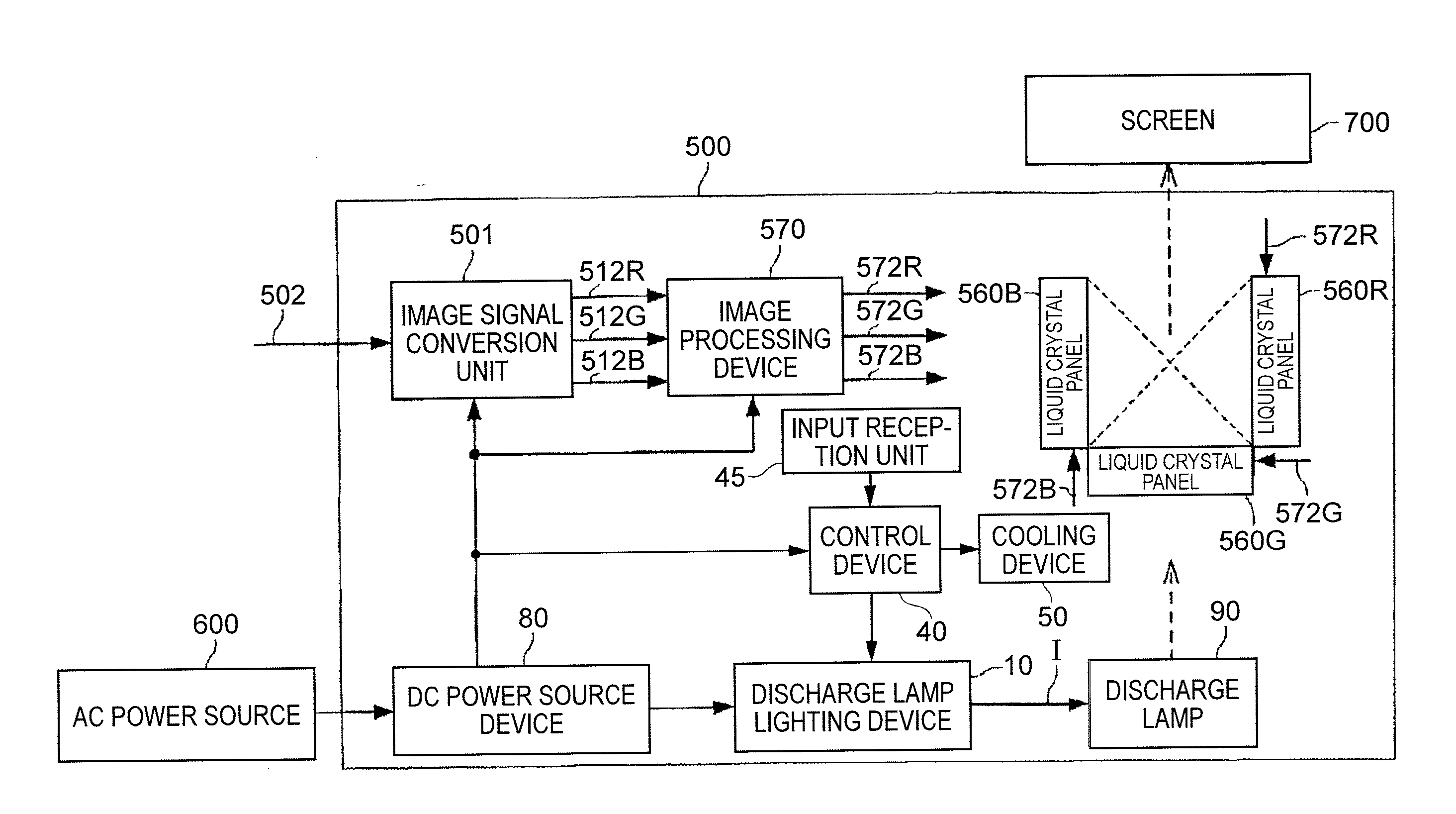
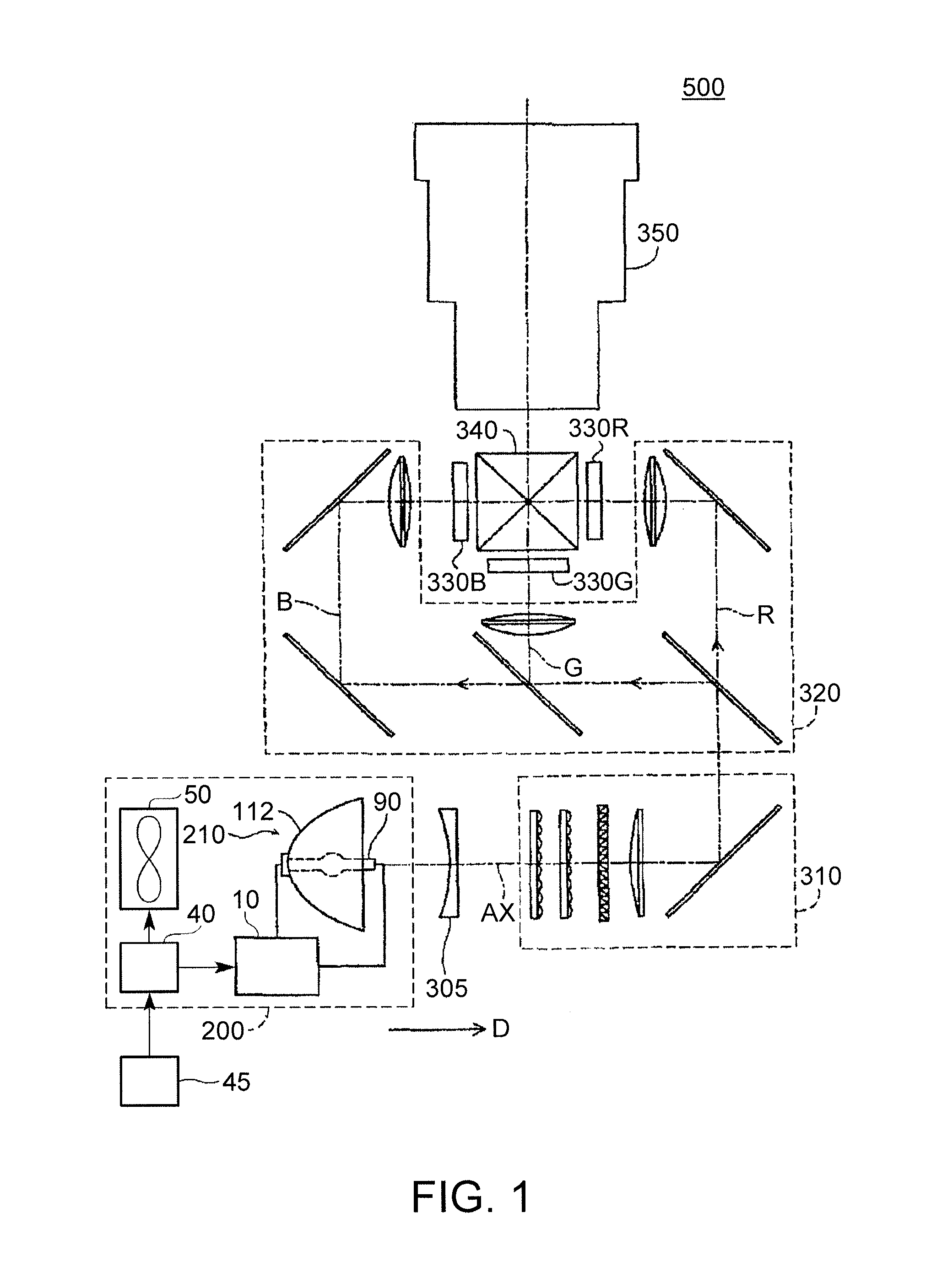
[0059]As illustrated in FIG. 1, a projector 500 of the present embodiment includes a light source apparatus 200, a collimating lens 305, an illumination optical system 310, a color separation optical system 320, three liquid crystal light valves (light modulation devices) 330R, 330G and 330B, a cross dichroic prism 340, and a projection optical system 350.

[0060]Light emitted from the light source apparatus 200 passes through the collimating lens 305 and is incident to the illumination optical system 310. The collimating lens 305 collimates the light from the light source apparatus 200.

[0061]The illumination optical system 310 adjusts the illuminance of the light emitted from the light source apparatus 200 so that the illuminance is uniformized on the liquid crystal light valves 330R, 330G and 330B. The illumination optical system 310 aligns polarization directions of the light emitted from the light source apparatus 200 in one direction. This is aimed at effectively using the light ...

second embodiment

[0193]A second embodiment is different from the first embodiment in terms of a current waveform.

[0194]In the following description, the same constituent elements as in the first embodiment are given the same reference numerals, and description thereof will be omitted in some cases.

[0195]FIG. 10 is a diagram illustrating an example of a driving current waveform DW2 of the present embodiment. FIG. 10 illustrates the driving current waveform DW2 before and after the input reception unit 45 receives a stop operation.

[0196]As illustrated in FIG. 10, the driving current waveform DW2 (driving current I) includes the steady lighting period PH1 and a heating period (second AC period) PH22. In the present embodiment, the driving current waveform DW2 transitions from the steady lighting period PH1 to the heating period PH22 when the input reception unit 45 receives the first stop operation.

[0197]The heating period PH22 alternately includes a first polarity period P12 in which the first polarit...

third embodiment

[0208]A third embodiment is different from the first embodiment in that a length of a second polarity period is larger than a length of a first polarity period in a heating period. In the following description, the same constituent elements as in the first embodiment are given the same reference numerals, and description thereof will be omitted in some cases.

[0209]FIG. 11 is a diagram illustrating an example of a driving current waveform DW3 of the present embodiment. FIG. 11 illustrates the driving current waveform DW3 before and after the input reception unit 45 receives a stop operation.

[0210]As illustrated in FIG. 11, the driving current waveform DW3 includes the steady lighting period PH1 and a heating period PH23 in which an alternating current is supplied to the discharge lamp 90. In the present embodiment, the driving current waveform DW3 transitions from the steady lighting period PH1 to the heating period PH23 when the input reception unit 45 receives the first stop operat...


PUM


Abstract

In a projector, a reflection mirror configured to reflect light emitted from a discharge lamp is disposed on a first end of a discharge lamp main body, a first electrode is disposed on the first end side, each of a first AC period and a second AC period alternately includes a first polarity period in which the first electrode serves as an anode and a second polarity period in which a second electrode serves as an anode, a controller causes a period to transition from the first AC period to the second AC period in a case where an input reception unit receives a stop operation on the projector, and an absolute value of a driving current of the second polarity period in the second AC period is greater than an absolute value of the driving current of the second polarity period in the first AC period.

Description

CROSS-REFERENCE[0001]This application is based upon and claims the benefit of priority from Japanese Patent Application Nos. 2015-042885 and 2015-042886, both filed Mar. 4, 2015; the entire contents of which are incorporated herein by reference.BACKGROUND[0002]1. Technical Field[0003]The present invention relates to a projector, and a control method for the projector.[0004]2. Related Art[0005]If an operation of a projector is stopped, the temperature of a discharge lamp provided in the projector decreases. Thus, mercury enclosed in the discharge lamp may condense and may be attached to an inner wall or electrodes of the discharge lamp. At this time, a mercury bridge may be generated as a result of the electrodes being connected to each other via mercury. If the mercury bridge is generated, the electrodes are short-circuited to each other, and thus the discharge lamp cannot be lighted.[0006]In relation to this problem, Japanese Patent No. 4070420 discloses a method in which, in order...

Claims


Application Information

Patent Timeline
Patent Type & Authority Applications(United States)
IPC IPC(8): H04N9/31H05B41/36H05B41/282
CPCH04N9/3155H05B41/36H05B41/2828H04N9/3144G03B21/16G03B21/2026G03B21/206H05B47/10Y02B20/00
Inventor SUZUKI, JUNICHITERASHIMA, TORU
Owner SEIKO EPSON CORP
Why Eureka
Try Eureka