Automated driving system

a driving system and automatic technology, applied in the direction of vehicle position/course/altitude control, process and machine control, instruments, etc., can solve the problems of cumbersome switching from manual driving to driving mode, difficult system recognition, and difficulty in complete recognition of obstacles on the system side, so as to reduce the convenience of automatic driving.

Active Publication Date: 2020-08-25
TOYOTA JIDOSHA KK
View PDF28 Cites 0 Cited by
  • Summary
  • Abstract
  • Description
  • Claims
  • Application Information

AI Technical Summary

Benefits of technology

[0005]This disclosure provides an automated driving system that can curb deterioration of the convenience of automated driving.
[0007]Regarding an obstacle that is present around the vehicle during operation in an automated driving mode, the user can recognize a situation where the obstacle has no influence on automated driving, whereas it may be difficult for the obstacle recognizing unit to correctly recognize the situation. In this situation, the automated driving system configured as described above is able to continue automated driving (avoid switching to manual driving), by excluding the obstacle from the obstacle recognition result through the input of the user. Namely, it is possible to curb deterioration of the convenience of automated driving.
[0022]According to the disclosure, it is possible to provide the automated driving system that can curb deterioration of the convenience of automated driving.

Problems solved by technology

According to the above technology, it is technically difficult to achieve complete recognition of obstacles on the system side.
Therefore, during operation of the vehicle in an automated driving mode, the automated driving may be interrupted and switched to manual driving, each time it becomes difficult for the system to correctly recognize an obstacle.
The switching of the driving mode to the manual driving is cumbersome for the driver, and the convenience of the automated driving may deteriorate.
Regarding an obstacle that is present around the vehicle during operation in an automated driving mode, the user can recognize a situation where the obstacle has no influence on automated driving, whereas it may be difficult for the obstacle recognizing unit to correctly recognize the situation.

Method used


Image

  • Automated driving system
  • Automated driving system
  • Automated driving system

Examples


first embodiment

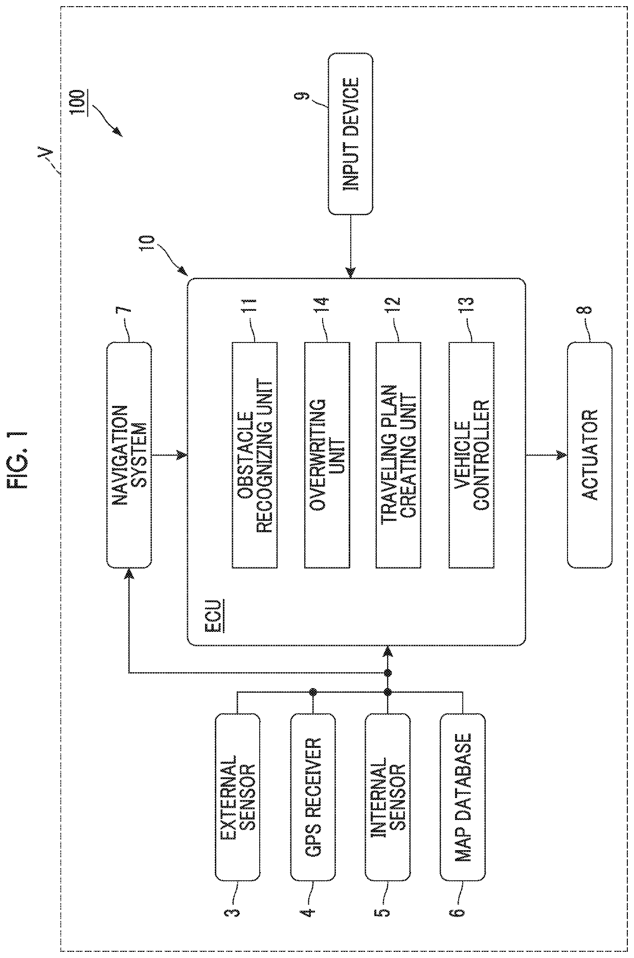
[0032]FIG. 1 is a block diagram showing the configuration of an automated driving system 100 of a first embodiment. As shown in FIG. 1, the automated driving system 100 is installed on a vehicle V, such as a passenger automobile. The automated driving system 100 is a system for causing the vehicle V to travel in an automated driving mode. The automated driving means vehicle control for causing the vehicle V to autonomously travel toward a preset destination, without requiring a user (including a driver, etc.) of the vehicle V to perform driving operation.

[0033]The automated driving system 100 includes an external sensor or sensors 3, GPS (Global Positioning System) receiver 4, internal sensor or sensors 5, map database 6, navigation system 7, actuators 8, input device 9, and an ECU (Electronic Control Unit) 10.

[0034]The external sensor 3 is a detection device that detects ambient surroundings (external conditions) as circumstances surrounding the vehicle V. The external sensor 3 inc...

second embodiment

[0063]Next, a second embodiment will be described. In the following, only the points in which the second embodiment is different from the first embodiment will be described, and repeated description will not be provided.

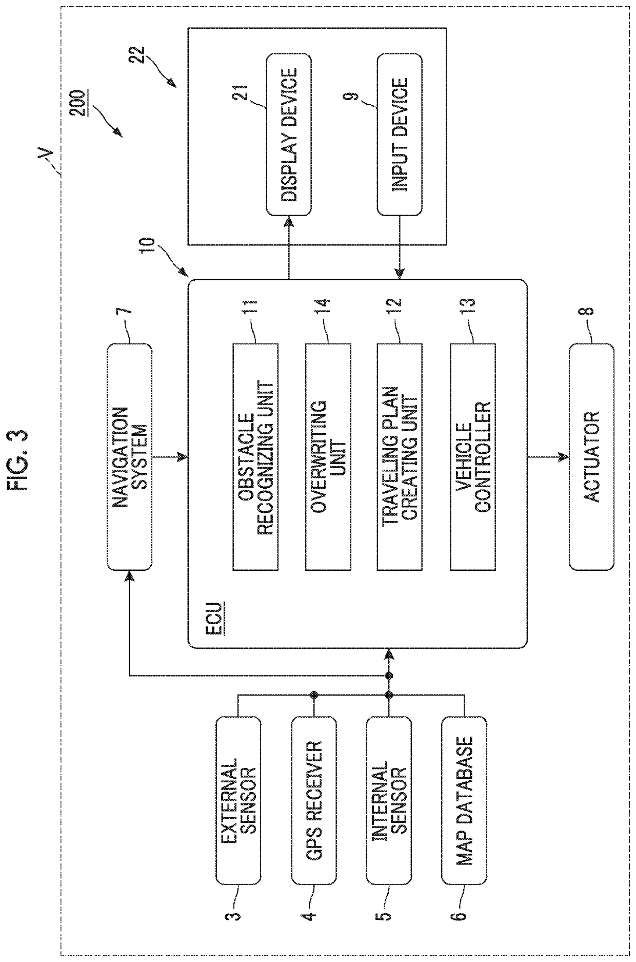
[0064]FIG. 3 is a block diagram showing the configuration of an automated driving system 200 of the second embodiment. As shown in FIG. 3, the automated driving system 200 further includes a display device 21. The display device 21 is a presenting unit that presents an obstacle recognition result of the obstacle recognizing unit 11 to the user. The display device 21 allows the obstacle recognition result to be shared by the system side and the user. In this embodiment, the display device 21 is also used as the input device 9, and a touch panel 22 is used as the input device 9 and the display device 21.

[0065]The overwriting unit 14 of the automated driving system 200 can perform partial overwriting operation as operation to exclude (or ignore) a part of two or more ob...

third embodiment

[0073]Next, the third embodiment will be described. In the following, only the points in which the third embodiment is different from the first embodiment will be described, and repeated description will not be provided.

[0074]FIG. 5 is a block diagram showing the configuration of an automated driving system 300 of the third embodiment. As shown in FIG. 5, the ECU 10 of the automated driving system 300 further includes a reliability calculating unit 15.

[0075]The reliability calculating unit 15 calculates the reliability of the obstacle recognition result obtained by the obstacle recognizing unit 11. The reliability is an indicator that indicates the authenticity of the obstacle recognition result, or the degree thereof. The reliability may be expressed by a level, numerical value, high or low, presence or absence, or the like, for example. As the reliability is higher (or when there is reliability), it can be determined that the obstacle recognition result is authentic. The reliabili...


PUM


Abstract

An automated driving system includes at least one electronic control unit configured to: recognize at least one obstacles around a vehicle, based on ambient surroundings of the vehicle; create a traveling plan of the vehicle, based on the ambient surroundings and a result of recognition of the at least one obstacles; control the vehicle using an actuator installed on the vehicle, based on the traveling plan; and perform, according to input from a user of the vehicle, overwriting operation to change the result of recognition of the at least one obstacles used for creation of the traveling plan.

Description

INCORPORATION BY REFERENCE[0001]The disclosure of Japanese Patent Application No. 2017-048848 filed on Mar. 14, 2017 including the specification, drawings and abstract is incorporated herein by reference in its entirety.BACKGROUND1. Technical Field[0002]The disclosure relates to an automated driving system.2. Description of Related Art[0003]As one example of automated driving system, an automated driving control system described in Japanese Patent Application Publication No. 2016-137819 (JP 2016-137819 A), for example, is known. The automated driving system recognizes an obstacle or obstacles around a vehicle, and performs automated driving of the vehicle, based on the result of recognition of the obstacle(s) and ambient surroundings of the vehicle.SUMMARY[0004]According to the above technology, it is technically difficult to achieve complete recognition of obstacles on the system side. Therefore, during operation of the vehicle in an automated driving mode, the automated driving ma...

Claims


Application Information

Patent Timeline
Patent Type & Authority Patents(United States)
IPC IPC(8): G05D1/00B60W30/00G05D1/02G08G1/16
CPCG05D1/0214G05D1/0238G05D1/0088B60W30/00G05D1/0055G08G1/165G08G1/166G05D1/0274G05D1/0257G05D2201/0213B60W30/09B60W30/0956B60W2050/146B60W50/085B60W2540/215B60W2554/00B60W60/007B60W2556/20B60W2554/4041B60W2554/20B60W60/0016B60W2552/30B60W2554/4044B60W2554/4026B60W2554/4029B60W2552/50B60W2554/80B60W2552/05B60W40/114B60W2520/105B60W2520/14B60W2520/125B60W2520/28B60W2420/403B60W2420/52
Inventor SUGAIWA, TAISUKEICHIKAWA, KENTAROURANO, HIROMITSUSATO, KUNIHITOHIRANO, MAIKO
Owner TOYOTA JIDOSHA KK
Why Eureka
Try Eureka