Expandable intervertebral cage

a cage and vertebral technology, applied in the field of dissection and fusion of vertebrae, can solve the problems of high risk of nerve injury, rare technique practiced today, and destruction of a large portion of the disc spa

Active Publication Date: 2016-09-15
SPINEX TEC
View PDF4 Cites 14 Cited by
  • Summary
  • Abstract
  • Description
  • Claims
  • Application Information

AI Technical Summary

Problems solved by technology

However, the technique is seldom practiced today due to numerous disadvantages including lengthy operation time, destruction of a large portion of the disc space, high risk of nerve injury, and hip pain after harvesting the bone graft.
However, the device is primarily used for distraction and not subsequent vertebral fusion.
The device would not work as a fusion device, because once the pull arm is disconnected from the device, the device will not be stable enough to maintain proper spacing of the vertebrae until fusion can occur.
The endplates of the device are also solid and do not permit bone growth for successful fusion
The curable polymer and disabling of the device are necessary because the device could not adequately support the distracted disc space.
The base plates of the device have at least two or more degrees of freedom, collectively, in a distracted position and are therefore not stable under the loads encountered supporting the disc space.
Absent injection of the polymer, and the support and control supplied by the implanting physician via the removable distraction tool, the base plates would collapse, which could cause severe damage to the vertebral bodies.

Method used


Image

  • Expandable intervertebral cage
  • Expandable intervertebral cage
  • Expandable intervertebral cage

Examples


Embodiment Construction

[0042]In the following detailed description of the present invention, numerous specific details are set forth in order to provide a thorough understanding of the present invention. However, one skilled in the art will recognize that the present invention may be practiced without these specific details. In other instances, well-known methods, procedures, and components have not been described in detail so as to not unnecessarily obscure aspects of the present invention. U.S. Pat. No. 8,628,577, invented by the inventor of the present application, discloses a stable intervertebral body fusion and distraction device. This patent is hereby incorporated herein by reference in its entirety other than the summary of the invention, claims and any express definitions set forth therein.

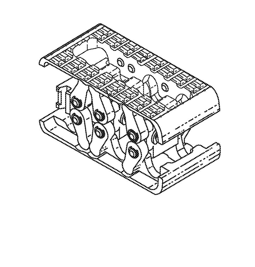
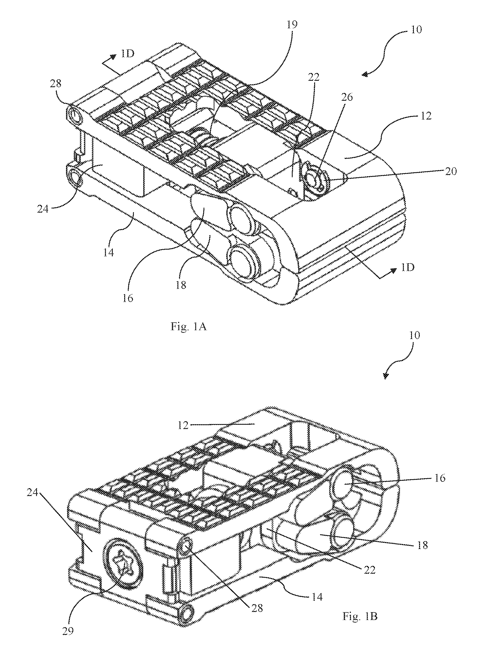
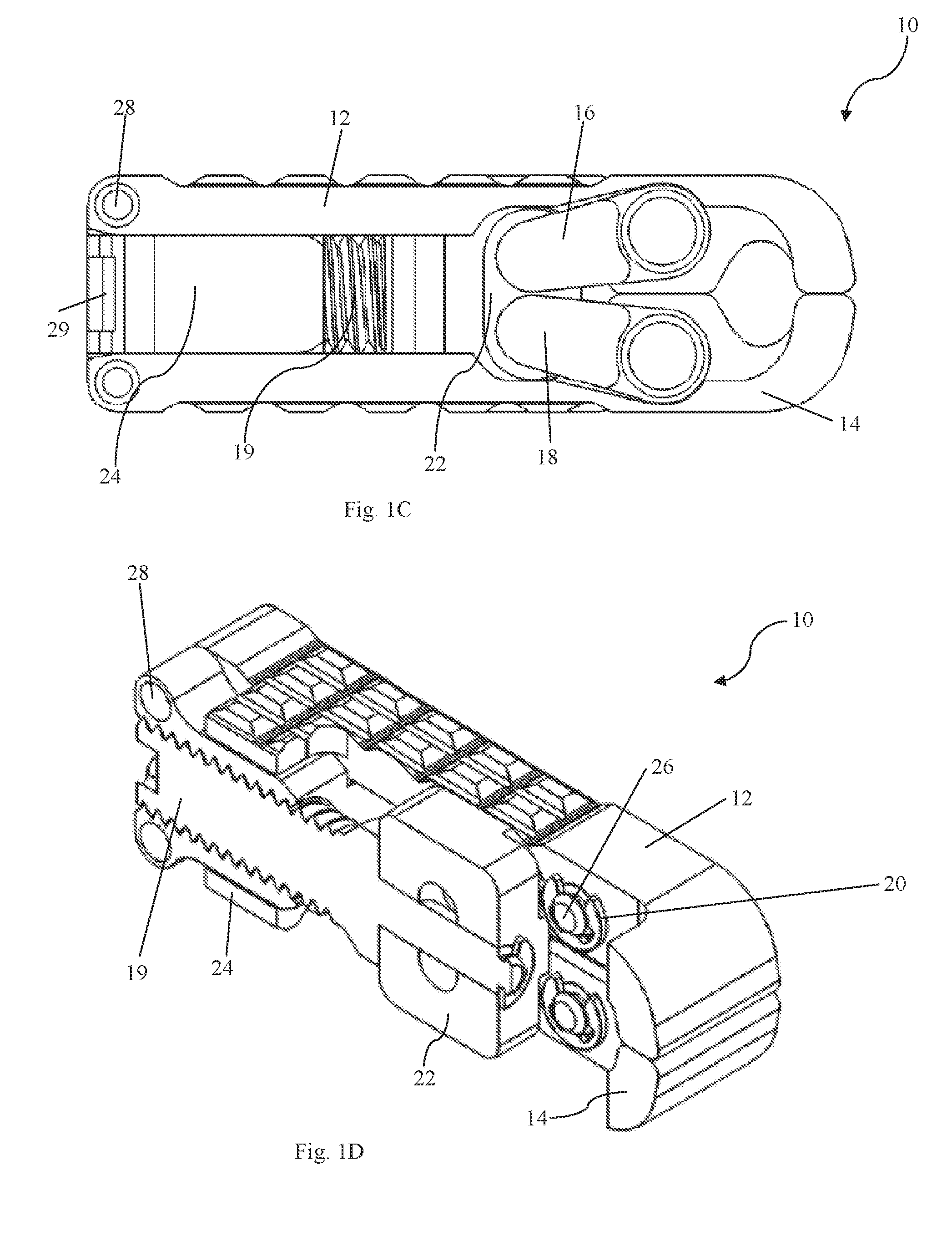
[0043]FIG. 1A is a perspective view of expandable intervertebral cage device 10, as seen from a distal end. FIG. 1B shows the same intervertebral cage device 10 from an opposite, proximal end. As shown in FIGS....


PUM


Abstract

An expandable intervertebral cage device includes a first base plate and a second base plate, a proximal block with internal threading that mechanically couples the first base plate and the second base plate, and a distal block comprising an internal passage. The device has exactly two arm assemblies, one on each side. Each arm assembly includes a first arm mechanically coupled to the first base plate and the distal block, and a second arm is mechanically coupled to the second base plate and the distal block. A screw is arranged partially within the internal threading of the proximal block and passes through the internal passage of the distal block, such that rotation of the screw relative to the proximal block causes a change in distance between the proximal block and the distal block, and a corresponding change in the spacing and lordosis of the device.

Description

RELATED APPLICATIONS[0001]The present application is a Continuation in Part of U.S. patent application Ser. No. 14 / 242,451 entitled “EXPANDABLE INTERVERTEBRAL CAGE”, filed Apr. 1, 2014, which is incorporated herein by reference in its entirety. This application is also related to PCT Application No. PCT / US2014 / 052913 entitled “EXPANDABLE INTERVERTEBRAL CAGE,” filed Aug. 27, 2014.TECHNICAL FIELD[0002]The present invention relates to the distraction and fusion of vertebral bodies. More specifically, the present invention relates to devices and associated methods for distraction and fusion of vertebral bodies that remain stable when implanted and facilitate fusion following their use for distraction to aid in the correction of spinal deformity by reducing a collapsed disc and establishing sagittal alignment, lordosis, or kyphosis.BACKGROUND[0003]The concept of intervertebral fusion for the cervical and lumbar spine following a discectomy was generally introduced in the 1960s. It involv...

Claims


Application Information

Patent Timeline
Patent Type & Authority Applications(United States)
IPC IPC(8): A61F2/44
CPCA61F2/447A61F2250/0006A61F2250/0009A61F2002/4475A61F2002/30471A61F2002/30507A61F2002/30538A61F2002/30556A61F2002/30593
Inventor JIMENEZ, OMAR F.SAFRIS, YEFIM
Owner SPINEX TEC
Why Eureka
Try Eureka