Coaxial superimposed multiple layer arbitrary angle rotary caging device

A technology of arbitrary angle and limit device, which is applied in the direction of position/direction control, instrument, control/adjustment system, etc., can solve the problems of inability to realize arbitrary angle control, complex structure of limit device, limited application range, etc., and achieve limit Flexible, simple structure, and wide-ranging effects

Active Publication Date: 2008-07-02
DG HUST MFG ENG RES INST +1
View PDF2 Cites 9 Cited by
  • Summary
  • Abstract
  • Description
  • Claims
  • Application Information

AI Technical Summary

Problems solved by technology

[0003] The purpose of the present invention is to provide a coaxially stacked multi-layer arbitrary angle rotation limiting device in order to overcome the problem that the existing limiting device has a complex structure, cannot realize arbitrary angle control, and has a limited application range.

Method used


Image

  • Coaxial superimposed multiple layer arbitrary angle rotary caging device
  • Coaxial superimposed multiple layer arbitrary angle rotary caging device

Examples


Embodiment 1

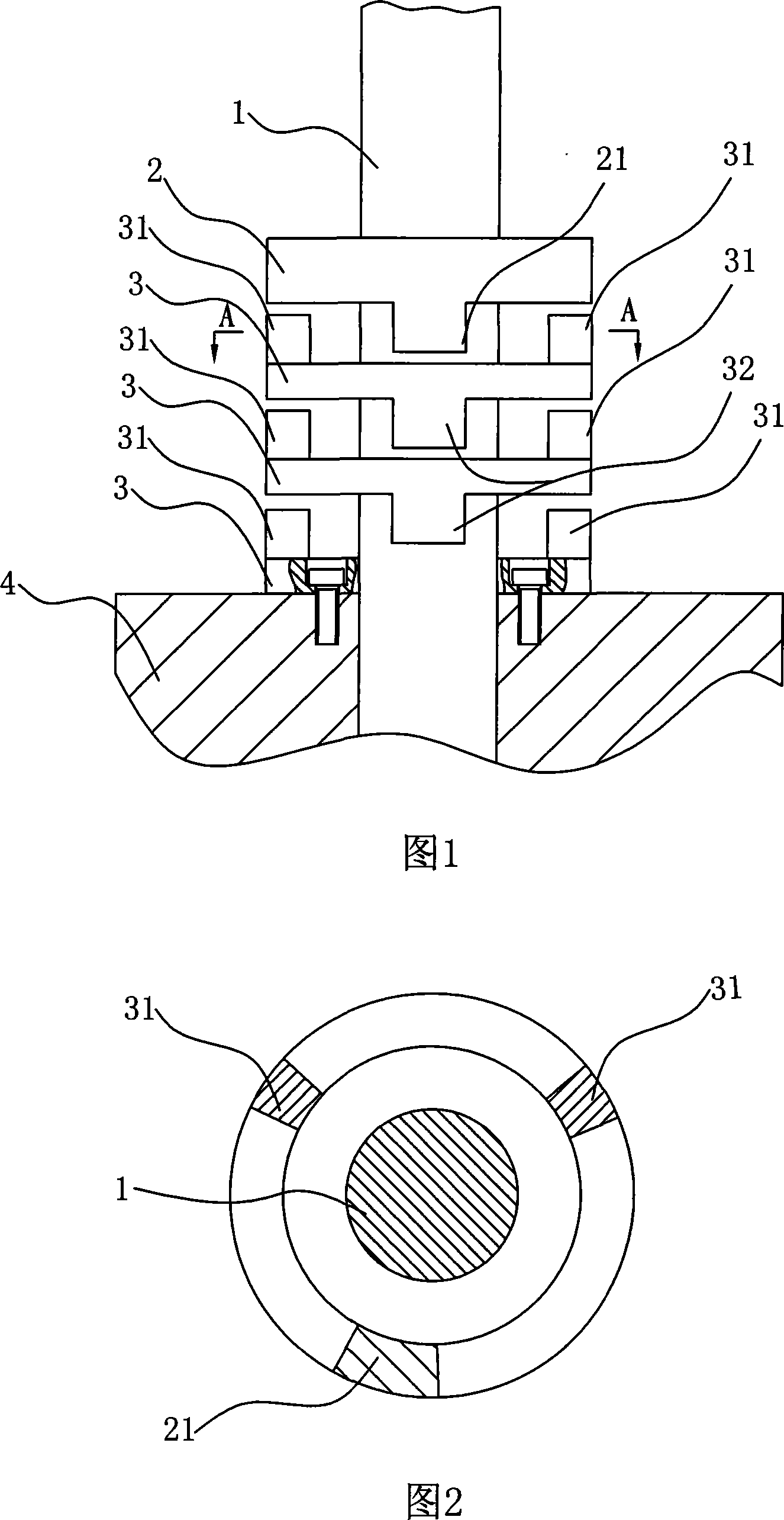
[0013] Embodiment 1: As shown in Figures 1 and 2: a coaxial stacked multi-layer rotation limit device at any angle, which includes a rotary shaft 1, a follow-up dial ring 2, a limit stop ring 3 and a machine base 4; The follow-up dial ring 2, the limit stop ring 3 and the machine base 4 are sequentially installed on the rotary shaft 1, the follow-up dial ring 2 is fixedly connected with the rotary shaft 1, and the limit stop ring 3 and the machine base 4 are set on the rotary shaft 1, the device includes at least one limit stop ring 3, the limit stop ring 3 close to the machine base is fixedly connected with the machine base 4, and the follow-up dial ring 2 is adjacent to the limit stop ring 3 An angular rotation limiting device is arranged between the limit stop ring 3; an axially protruding toggle foot 21 is arranged on the outer ring of the follow-up dial ring 3; There are two protruding gear feet 31, and the other side of the limit stop ring 3 is correspondingly provided w...

Embodiment 2

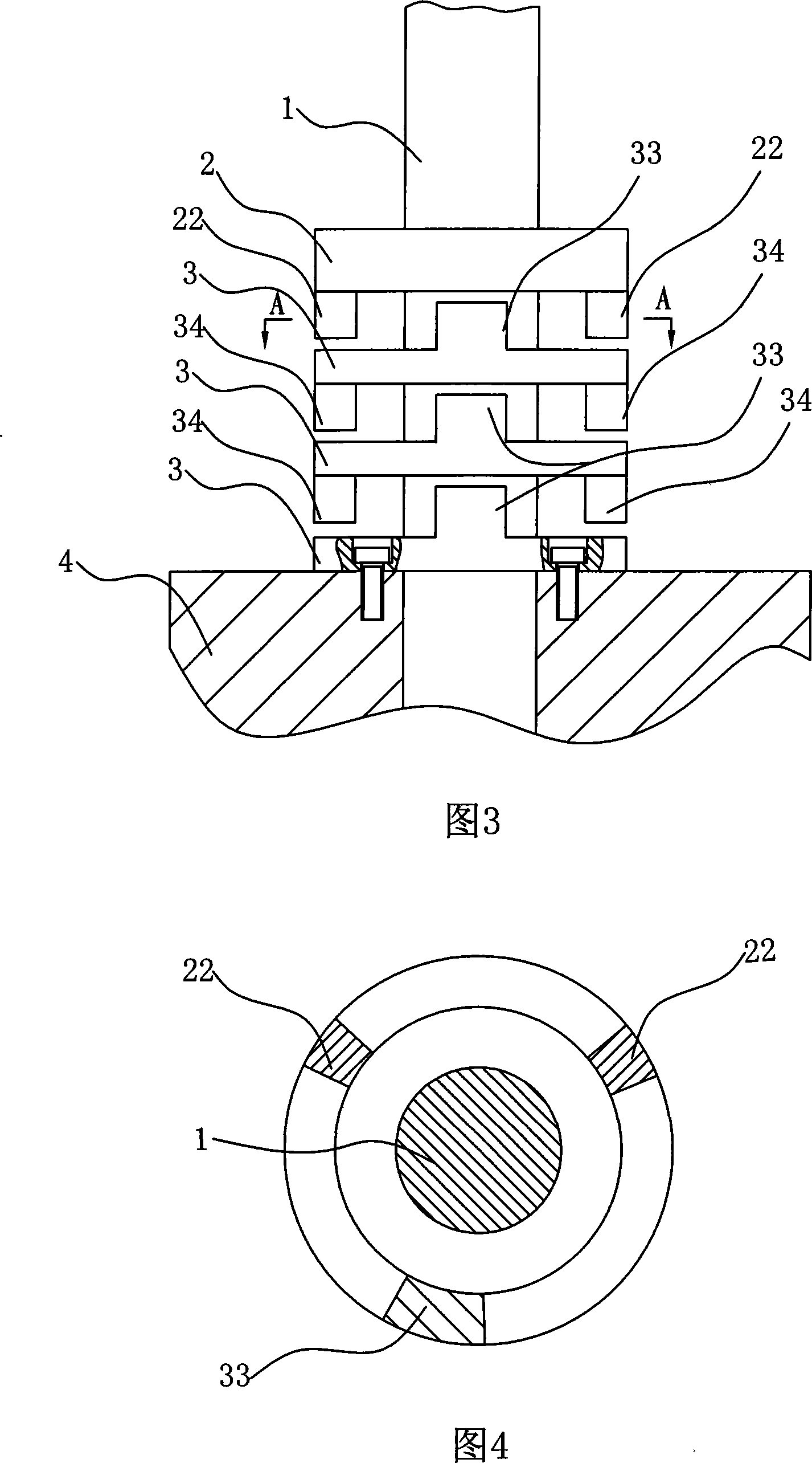
[0014] Embodiment 2: As shown in Figures 3 and 4: a coaxial stacked multi-layer rotation limit device at any angle, which includes a rotary shaft 1, a follower ring 2, a limit stop ring 3 and a machine base 4; The follow-up dial ring 2, the limit stop ring 3 and the machine base 4 are sequentially installed on the rotary shaft 1, the follow-up dial ring 2 is fixedly connected with the rotary shaft 1, and the limit stop ring 3 and the machine base 4 are set on the rotary shaft 1, the device includes at least one limit stop ring 3, the limit stop ring 3 close to the machine base is fixedly connected with the machine base 4, and the follow-up dial ring 2 is adjacent to the limit stop ring 3 The limit stop ring 3 is provided with an angular rotation limit device; the outer ring of the follow-up dial ring 2 is provided with two axially protruding gear feet 22; The protruding toggle pin 33, the other side of the limit stop ring 3 is correspondingly provided with two gear pins 34; th...


PUM


Abstract

The invention relates to the technical field of mechanical equipment, in particular to a coaxial overlaid position-limiting device which can rotate on multiple layers and at any angle, and comprises a revolving shaft, a servo poking ring, a stopper ring and a frame. The servo poking ring, the stopper ring and the frame are nested on the revolving shaft in turn, wherein the servo poking ring is fixedly connected with the revolving shaft, and the stopper ring and the frame are nested on the revolving shaft. The device includes at least one stopper ring and the stopper ring which is close to the frame is fixedly connected with the frame. An angle-rotational limiting device is arranged between the servo poking ring and the stopper ring and between the neighboring stopper rings. The whole system can be adjusted to rotate at any angle in a direction by adjusting the numbers of the stopper rings and the rotating angle of the angle-rotational limiting device. The invention is characterized in simple structure, multiple-angle position limiting, flexible position limiting, convenient application and wide adaptation.

Description

technical field [0001] The invention relates to the technical field of mechanical equipment, in particular to a coaxially stacked multi-layer arbitrary angle rotation limiting device. Background technique [0002] In some rotary instruments and equipment, reliable control of the rotary angle and multi-angle control are often required for motion control and protection of equipment components. Although proximity switches and travel switches can realize angle control, they are unstable and unreliable. Therefore, the best way to reliably control the rotation angle is the control method of the mechanical structure; generally, a special rotation limit device is used to achieve reliable rotation angle control. However, according to the retrieval results, although the existing rotary limiting mechanism can realize reliable limiting, it cannot realize multi-angle or arbitrary angle limiting. For example: the patent No.: CN01240598.1 patent "360° azimuth limit mechanism of simulatio...

Claims


Application Information

Patent Timeline
Patent Type & Authority Applications(China)
IPC IPC(8): G05D3/00
Inventor 李斌段正澄黄禹蔡立兵龚时华彭芳瑜王春明
Owner DG HUST MFG ENG RES INST
Why Eureka
Try Eureka